~
~
Z
A
Z
B
Z
L1
A
B
I
M
Fault
IED
Z
L2
M
C
Line 1
Line 2
ANSI09000025_2_en.vsd
ANSI09000025 V2 EN-US
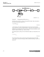
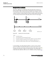
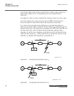
Figure 259:
Two parallel lines. Influence from parallel line to the through fault
current: I
M
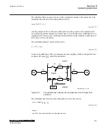
The minimum theoretical current setting for the overcurrent protection function (Imin)
will be:
Imin MAX I
fA
I
fB
I
M
,
,
(
)
³
EQUATION82 V1 EN-US
(Equation 418)
Where I
fA
and I
fB
have been described in the previous paragraph. Considering the
safety margins mentioned previously, the minimum setting (Is) for the instantaneous
phase overcurrent protection 3-phase output is then:
Is
³
1.3·Imin
EQUATION83 V2 EN-US
(Equation 419)
The protection function can be used for the specific application only if this setting
value is equal or less than the maximum phase fault current that the IED has to clear.
The IED setting value
Pickup
is given in percentage of the primary base current value,
IBase
. The value for
Pickup
is given from this formula:
100
Is
Pickup
IBase
=
×
ANSIEQUATION1147 V1 EN-US
(Equation 420)
Section 9
1MRK 504 163-UUS A
Current protection
518
Transformer protection RET670 2.2 ANSI
Application manual
Summary of Contents for RELION RET670
Page 1: ...RELION 670 SERIES Transformer protection RET670 Version 2 2 ANSI Application manual ...
Page 2: ......
Page 48: ...42 ...
Page 64: ...58 ...
Page 74: ...68 ...
Page 104: ...98 ...
Page 194: ...188 ...
Page 518: ...512 ...
Page 618: ...612 ...
Page 648: ...642 ...
Page 666: ...660 ...
Page 672: ...666 ...
Page 682: ...676 ...
Page 844: ...838 ...
Page 868: ...862 ...
Page 956: ...950 ...
Page 964: ...958 ...
Page 1004: ...998 ...
Page 1014: ...1008 ...
Page 1015: ...1009 ...


