9.2.3.2
Setting example
GUID-20729467-24AB-42F0-9FD1-D2959028732E v1
Directional phase overcurrent protection, four steps can be used in different ways,
depending on the application where the protection is used. A general description is
given below.
The pickup current setting of the inverse time protection, or the lowest current step of
the definite time protection, must be defined so that the highest possible load current
does not cause protection operation. The protection reset current must also be
considered so that a short peak of overcurrent does not cause the operation of a
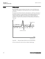
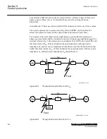
protection even when the overcurrent has ceased. This phenomenon is described in
Figure
.
Pickup current
Current I
The IED does not reset
Line phase current
Time t
Reset current
ANSI09000146-en-1.vsd
ANSI09000146 V1 EN-US
Figure 262:
Pickup and reset current for an overcurrent protection
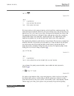
The lowest setting value can be written according to Equation
.
Section 9
1MRK 504 163-UUS A
Current protection
526
Transformer protection RET670 2.2 ANSI
Application manual
Summary of Contents for RELION RET670
Page 1: ...RELION 670 SERIES Transformer protection RET670 Version 2 2 ANSI Application manual ...
Page 2: ......
Page 48: ...42 ...
Page 64: ...58 ...
Page 74: ...68 ...
Page 104: ...98 ...
Page 194: ...188 ...
Page 518: ...512 ...
Page 618: ...612 ...
Page 648: ...642 ...
Page 666: ...660 ...
Page 672: ...666 ...
Page 682: ...676 ...
Page 844: ...838 ...
Page 868: ...862 ...
Page 956: ...950 ...
Page 964: ...958 ...
Page 1004: ...998 ...
Page 1014: ...1008 ...
Page 1015: ...1009 ...


