background image

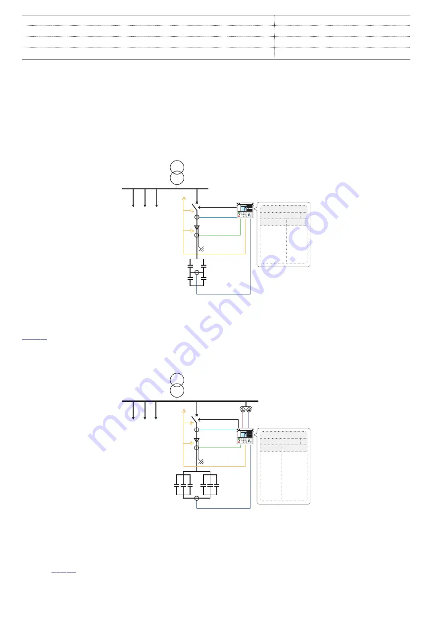
Standard configuration A is pre-configured for H-bridge
connected capacitor banks. Three-phase current unbalance
protection is used for unbalance.

Standard configuration B offers directional earth-fault
protection, residual voltage protection, overvoltage protection
and undervoltage protection functions. It is pre-configured for
double star connected capacitor banks. Single current
unbalance protection is used for unbalance.

The second and third stage of the residual voltage protection in
the standard configuration B can be used as voltage-based
unbalance protection mainly for single star connected capacitor
banks, with unearthed star point. Dedicated voltage input Uob
is used for this purpose. This functionality is available in
standard configuration B and needs to be configured before it is
taken into use.

3I

R

L

Clear

ESC

I

O

U12  0. 0 kV

P  0.00 kW

Q  0.00 kVAr

IL2   0  A

A

REV615

Std. conf.
ANSI

IEC

50L/50NL
50P/51P
51C
51NC-2
51P/51N
55TD

ARC
3I>>>
3I> 3I<
3dI>C
3I>/Io>
TD>

A

Io

3I

unb

GUID-B7F0755C-006A-4806-91D3-8C290EE3ECA0 V1 EN

Figure 3.

Protection of a H-bridge connected capacitor bank

Figure 3

 illustrates the protection of an H-bridge connected

capacitor bank. Standard configuration A is used with overload,
three-phase connected current unbalance and undercurrent

protection for the capacitor bank. Overcurrent and earth-fault
protection functions are used for protecting the feeder cable
and capacitor bank combination.

3I

REV615

Std. conf.
ANSI

IEC

27/59/59G
50L/50NL
50P/51P
51C
51NC-1
51P/51N
55TD
67N

3U</3U>/Uo>
ARC
3I>>>
3I> 3I<
dI>C
3I>/Io>
TD>
Io>

B

3U

Uo

R

L

Clear

ESC

I

O

U12  0. 0 kV

P  0.00 kW

Q  0.00 kVAr

IL2   0  A

A

Io

I

unb

GUID-5F33A1B7-2B6F-4CFA-9DD6-71E633C46846 V1 EN

Figure 4.

Protection of a double star connected capacitor bank in a distribution network with a compensated or isolated neutral

Protection of a double star connected capacitor bank in a
distribution network with a compensated or isolated neutral is
shown in 

Figure 4

. Standard configuration B is used with

overload, single phase connected current unbalance and

undercurrent protection for the capacitor bank. Overcurrent
and directional earth-fault protetion functions are used for
protecting the feeder cable and capacitor bank combination.

Capacitor Bank Protection and Control

1MRS757952 D

REV615


Product version: 5.0 FP1


8

ABB

Summary of Contents for RELION REV615

Page 1: ... RELION 615 SERIES Capacitor Bank Protection and Control REV615 Product Guide ...

Page 2: ...ction and ordering data 47 25 Accessories and ordering data 48 26 Tools 49 27 Cyber security 50 28 Terminal diagrams 51 29 Certificates 53 30 References 53 31 Functions codes and symbols 54 32 Document revision history 57 Disclaimer The information in this document is subject to change without notice and should not be construed as a commitment by ABB ABB assumes no responsibility for any errors th...

Page 3: ...s relays support a range of communication protocols including IEC 61850 with Edition 2 support process bus according to IEC 61850 9 2 LE IEC 60870 5 103 Modbus and DNP3 Profibus DPV1 communication protocol is supported by using the protocol converter SPA ZC 302 2 Standard configurations REV615 is available in two alternative standard configurations The standard signal configuration can be altered ...

Page 4: ...tocols HSR PRP RSTP I Io Limit value supervision Load profile record RTD mA measurement optional Symmetrical components 7 Analog interface types 1 Current transformer Voltage transformer 1 Conventional transformer inputs ALSO AVAILABLE Disturbance and fault recorders Event log and recorded data High Speed Output module optional Local Remote push button on LHMI Self supervision Time synchronization ...

Page 5: ... Event log and recorded data High Speed Output module optional Local Remote push button on LHMI Self supervision Time synchronization IEEE 1588 v2 SNTP IRIG B User management Web HMI Master Trip Lockout relay 94 86 PQM3I PQM3I 2 TCS TCM MCS 3I MCS 3I CBCM CBCM OPTS OPTM 18 MAP MAP 2xRTD 1xmA Io 51N 2 2 Io 67N 1 Io 67N 2 2 3U 27 U2 47O U1 47U 2 3U 59 Uo 59G FUSEF 60 2 I2 46 3I 50P 51P 3 ARC 50L 50N...

Page 6: ...erload protection for shunt capacitor banks COLPTOC 1 1 Current unbalance protection for shunt capacitor banks CUBPTOC 1 4 1 4 Three phase current unbalance protection for shunt capacitor banks HCUBPTOC 1 4 1 4 Shunt capacitor bank switching resonance protection current based SRCPTOC 1 1 Power quality Current total demand distortion CMHAI 1 5 1 6 Voltage total harmonic distortion VMHAI 1 6 Voltage...

Page 7: ...nd thermal overload protection as well as non directional earth fault protection Additionally the standard configuration B includes directional earth fault protection residual voltage protection overvoltage protection and undervoltage protection functions Enhanced with optional hardware and software the relay also features three light detection channels for arc fault protection of the circuit brea...

Page 8: ... of a H bridge connected capacitor bank Figure 3 illustrates the protection of an H bridge connected capacitor bank Standard configuration A is used with overload three phase connected current unbalance and undercurrent protection for the capacitor bank Overcurrent and earth fault protection functions are used for protecting the feeder cable and capacitor bank combination 3I REV615 Std conf ANSI I...

Page 9: ...ent and earth fault protection functions are used for protecting the feeder cable and harmonic filter circuit combination 3U Uo R L Clear ESC I O U12 0 0 kV P 0 00 kW Q 0 00 kVAr IL2 0 A A 3I REV615 Std conf ANSI IEC 27 59 59G 50L 50NL 50P 51P 51C 51P 55TD 67N 3U 3U Uo ARC 3I 3I 3I 3I TD Io B Uob Io GUID 9C6F9938 FB13 4615 842A 9606411B47FC V1 EN Figure 6 Protection of a single star connected capa...

Page 10: ...OM600S features a Web browser based HMI which provides a customizable graphical display for visualizing single line mimic diagrams for switchgear bay solutions The SLD feature is especially useful when 615 series relays without the optional single line diagram feature are used The Web HMI of COM600S also provides an overview of the whole substation including relay specific single line diagrams whi...

Page 11: ...increase the number of available binary inputs and outputs If the amount of available binary inputs or outputs of the chosen standard configuration is not sufficient the standard configuration can be modified to release some binary inputs or outputs which have originally been configured for other purposes when applicable or an external input or output module for example RIO600 can be integrated to...

Page 12: ...protection relay has the following power quality monitoring functions Voltage variation Voltage unbalance Current harmonics Voltage harmonics The voltage unbalance and voltage variation functions are used for measuring short duration voltage variations and monitoring voltage unbalance conditions in power transmission and distribution networks The voltage and current harmonics functions provide a m...

Page 13: ...counters etc History view GUID CDF1DC16 AF90 406F B21B EF6C7F60BCCA V1 EN Figure 8 Recording and event capabilities overview 12 Condition monitoring The condition monitoring functions of the relay constantly monitor the performance and the condition of the circuit breaker The monitoring comprises the spring charging time SF6 gas pressure the travel time and the inactivity time of the circuit break...

Page 14: ... protect the relay from unauthorized access and to maintain information integrity the relay is provided with a four level role based authentication system with administrator programmable individual passwords for the viewer operator engineer and administrator levels The access control applies to the local HMI the Web HMI and PCM600 18 Inputs and outputs The relay is equipped with three phase curren...

Page 15: ... also the full support of standard device mode functionality supporting different test applications Control applications can utilize the new safe and advanced station control authority feature The IEC 61850 communication implementation supports monitoring and control functions Additionally parameter settings disturbance recordings and fault records can be accessed using the IEC 61850 protocol Dist...

Page 16: ...entical Ethernet ports dedicated for one network connection The protocols rely on the duplication of all transmitted information and provide a zero switch over time if the links or switches fail thus fulfilling all the stringent real time requirements of substation automation In PRP each network node is attached to two independent networks operated in parallel The networks are completely separated...

Page 17: ...h with standard Rapid Spanning Tree Protocol RSTP support The managed switch controls the consistency of the loop routes the data and corrects the data flow in case of a communication switch over The relays in the ring topology act as unmanaged switches forwarding unrelated data traffic The Ethernet ring solution supports the connection of up to 30 615 series relays If more than 30 relays are to b...

Page 18: ...erent masters Besides basic standard functionality the relay supports changing of the active setting group and uploading of disturbance recordings in IEC 60870 5 103 format Further IEC 60870 5 103 can be used at the same time with the IEC 61850 protocol DNP3 supports both serial and TCP modes for connection up to five masters Changing of the active setting and reading fault records are supported D...

Page 19: ...eration Required accuracy of grandmaster clock is 1 µs The relay can work as a master clock per BMC algorithm if the external grandmaster clock is not available for short term The IEEE 1588 support is included in all variants having a redundant Ethernet communication module In addition the relay supports time synchronization via Modbus DNP3 and IEC 60870 5 103 serial communication protocols Table ...

Page 20: ...iary voltage supply under quiescent Pq operating condition DC 13 0 W nominal 18 0 W max AC 16 0 W nominal 21 0 W max DC 13 0 W nominal 18 0 W max Ripple in the DC auxiliary voltage Max 15 of the DC value at frequency of 100 Hz Fuse type T4A 250 V Table 8 Energizing inputs Description Value Rated frequency 50 60 Hz Current inputs Rated current In 0 2 1 A1 1 5 A2 Thermal withstand capability Continu...

Page 21: ...e three wire measurement 25 Ω per lead Isolation 2 kV inputs to protective earth Response time 4 s RTD resistance sensing current Maximum 0 33 mA rms Operation accuracy Resistance Temperature 2 0 or 1 Ω 1 C 10 Ω copper 2 C mA inputs Supported current range 0 20 mA Current input impedance 44 Ω 0 1 Operation accuracy 0 5 or 0 01 mA Table 11 Signal output X100 SO1 Description Value Rated voltage 250 ...

Page 22: ... the control circuit time constant L R 40 ms at 48 110 220 V DC two contacts connected in series 5 A 3 A 1 A Minimum contact load 100 mA at 24 V AC DC Trip circuit supervision TCS Control voltage range 20 250 V AC DC Current drain through the supervision circuit 1 5 mA Minimum voltage over the TCS contact 20 V AC DC 15 20 V Table 14 Single pole power output relays Description Value Rated voltage 2...

Page 23: ...lated Logic level 5 V TTL Current consumption 4 mA Power consumption 20 mW 1 According to the 200 04 IRIG standard Table 18 Degree of protection of flush mounted protection relay Description Value Front side IP 54 Rear side connection terminals IP 20 Table 19 Environmental conditions Description Value Operating temperature range 25 55ºC continuous Short time service temperature range 40 85ºC 16h 1...

Page 24: ...C 60255 26 class III 10 V m f 900 MHz ENV 50204 IEC 60255 26 class III 20 V m rms f 80 1000 MHz IEEE C37 90 2 2004 Fast transient disturbance test IEC 61000 4 4 IEC 60255 26 IEEE C37 90 1 2002 All ports 4 kV Surge immunity test IEC 61000 4 5 IEC 60255 26 Communication 1 kV line to earth Other ports 4 kV line to earth 2 kV line to line Power frequency 50 Hz magnetic field immunity test IEC 61000 4 ...

Page 25: ... µV m peak 56 dB µV m average measured at 3 m distance 3 6 GHz 80 dB µV m peak 60 dB µV m average measured at 3 m distance Table 21 Insulation tests Description Type test value Reference Dielectric tests 2 kV 50 Hz 1 min 500 V 50 Hz 1 min communication IEC 60255 27 Impulse voltage test 5 kV 1 2 50 μs 0 5 J 1 kV 1 2 50 μs 0 5 J communication IEC 60255 27 Insulation resistance measurements 100 MΩ 50...

Page 26: ...h 3 h at 25 C 55 C IEC60068 2 14 Storage test 96 h at 40ºC 96 h at 85ºC IEC 60068 2 1 IEC 60068 2 2 Table 24 Product safety Description Reference LV directive 2006 95 EC Standard EN 60255 27 2013 EN 60255 1 2009 Table 25 EMC compliance Description Reference EMC directive 2004 108 EC Standard EN 60255 26 2013 Table 26 RoHS compliance Description Complies with RoHS directive 2002 95 EC Capacitor Ban...

Page 27: ... to P backup No suppression 1 Set Operate delay time 0 02 s Operate curve type IEC definite time Measurement mode default depends on stage current before fault 0 0 In fn 50 Hz fault current in one phase with nominal frequency injected from random phase angle results based on statistical distribution of 1000 measurements 2 Includes the delay of the signal output contact 3 Includes the delay of the ...

Page 28: ...5 Peak to Peak No suppression 1 Measurement mode default depends on stage current before fault 0 0 In fn 50 Hz earth fault current with nominal frequency injected from random phase angle results based on statistical distribution of 1000 measurements 2 Includes the delay of the signal output contact 3 Maximum Start value 2 5 In Start value multiples in range of 1 5 20 Table 30 Non directional earth...

Page 29: ...lly 40 ms Reset ratio Typically 0 96 Retardation time 30 ms Operate time accuracy in definite time mode 1 0 of the set value or 20 ms Operate time accuracy in inverse time mode 5 0 of the theoretical value or 20 ms 3 Suppression of harmonics RMS No suppression DFT 50 dB at f n fn where n 2 3 4 5 Peak to Peak No suppression 1 Set Operate delay time 0 06 s Operate curve type IEC definite time Measur...

Page 30: ...Operating characteristics table Table 33 Transient intermittent earth fault protection INTRPTEF Characteristic Value Operation accuracy Uo criteria with transient protection Depending on the frequency of the measured current fn 2 Hz 1 5 of the set value or 0 002 Uo Operate time accuracy 1 0 of the set value or 20 ms Suppression of harmonics DFT 50 dB at f n fn where n 2 3 4 5 Table 34 Transient in...

Page 31: ...eter Function Value Range Step Start value NSPTOC 0 01 5 00 In 0 01 Time multiplier NSPTOC 0 05 15 00 0 01 Operate delay time NSPTOC 40 200000 ms 10 Operating curve type1 NSPTOC Definite or inverse time Curve type 1 2 3 4 5 6 7 8 9 10 11 12 13 14 15 17 18 19 1 For further reference see the Operation characteristics table Table 37 Residual overvoltage protection ROVPTOV Characteristic Value Operati...

Page 32: ...he theoretical value or 20 ms3 Suppression of harmonics DFT 50 dB at f n fn where n 2 3 4 5 1 Start value 1 0 Un Voltage before fault 1 1 Un fn 50 Hz undervoltage in one phase to phase with nominal frequency injected from random phase angle results based on statistical distribution of 1000 measurements 2 Includes the delay of the signal output contact 3 Minimum Start value 0 50 Start value multipl...

Page 33: ...n Value Range Step Start value PHPTOV 0 05 1 60 Un 0 01 Time multiplier PHPTOV 0 05 15 00 0 01 Operate delay time PHPTOV 40 300000 ms 10 Operating curve type1 PHPTOV Definite or inverse time Curve type 5 15 17 18 19 20 1 For further reference see the Operation characteristics table Table 43 Positive sequence undervoltage protection PSPTUV Characteristic Value Operation accuracy Depending on the fr...

Page 34: ... n fn where n 2 3 4 5 1 Negative sequence voltage before fault 0 0 Un fn 50 Hz negative sequence overvoltage with nominal frequency injected from random phase angle results based on statistical distribution of 1000 measurements 2 Includes the delay of the signal output contact Table 46 Negative sequence overvoltage protection NSPTOV main settings Parameter Function Value Range Step Start value NSP...

Page 35: ...ding on the frequency of the measured current fn 2 Hz 1 5 of the set value or 0 002 In Operate time accuracy 1 0 of the set value or 20 ms Reset time Typically 40 ms Retardation time 20 ms Table 50 Circuit breaker failure protection CCBRBRF main settings Parameter Function Value Range Step Current value CCBRBRF 0 05 2 00 In 0 05 Current value Res CCBRBRF 0 05 2 00 In 0 05 CB failure mode CCBRBRF 1...

Page 36: ...he delay of the heavy duty output contact 3 Normal power output 4 High speed output Table 52 Arc protection ARCSARC main settings Parameter Function Value Range Step Phase start value ARCSARC 0 50 40 00 In 0 01 Ground start value ARCSARC 0 05 8 00 In 0 01 Operation mode ARCSARC 2 Light only 3 BI controlled Table 53 Multipurpose protection MAPGAPC Characteristic Value Operation accuracy 1 0 of the ...

Page 37: ...hree phase overload protection for shunt capacitor banks COLPTOC main settings Parameter Function Value Range Step Start value overload COLPTOC 0 30 1 50 In 0 01 Alarm start value COLPTOC 80 120 1 Start value Un Cur COLPTOC 0 10 0 70 In 0 01 Time multiplier COLPTOC 0 05 2 00 0 01 Alarm delay time COLPTOC 500 6000000 ms 100 Un Cur delay time COLPTOC 100 120000 ms 100 Table 57 Current unbalance prot...

Page 38: ...lly 0 96 Operate time accuracy in definite time mode 1 of the theoretical value or 20 ms Operate time accuracy in IDMT mode 5 of the theoretical value or 20 ms Suppression of harmonics DFT 50 dB at f n fn where n 2 3 4 5 1 Fundamental frequency current 1 0 In current before fault 0 0 In fault current 2 0 Start value results based on statistical distribution of 1000 measurements 2 Includes the dela...

Page 39: ...ms or maximum 50 ms Retardation time Typically 0 96 Retardation time 35 ms Operate time accuracy in definite time mode 1 0 of the set value or 20 ms Suppression of harmonics 50 dB at f fn Table 62 Shunt capacitor bank switching resonance protection current based SRCPTOC main settings Parameter Function Value Range Step Alarm start value SRCPTOC 0 03 0 50 In 0 01 Start value SRCPTOC 0 03 0 50 In 0 ...

Page 40: ...rm inv 10 IEC Very inv 11 IEC inv 12 IEC Ext inv 13 IEC S T inv 14 IEC L T inv 15 IEC Def Time 17 Programmable 18 RI type 19 RD type Operating curve type voltage protection 5 ANSI Def Time 15 IEC Def Time 17 Inv Curve A 18 Inv Curve B 19 Inv Curve C 20 Programmable 21 Inv Curve A 22 Inv Curve B 23 Programmable Capacitor Bank Protection and Control 1MRS757952 D REV615 Product version 5 0 FP1 40 ABB...

Page 41: ...t value or 0 2 of reference voltage Reset ratio Typically 0 96 Swell 1 04 Dip Interruption Table 65 Voltage unbalance VSQVUB Characteristic Value Operation accuracy 1 5 of the set value or 0 002 Un Reset ratio Typically 0 96 Capacitor Bank Protection and Control 1MRS757952 D REV615 Product version 5 0 FP1 ABB 41 ...

Page 42: ...n 0 01 Max operate current CCSPVC 1 00 5 00 In 0 01 Table 69 Fuse failure supervision SEQSPVC Characteristic Value Operate time1 NPS function UFault 1 1 set Neg Seq voltage Lev 33 ms UFault 5 0 set Neg Seq voltage Lev 18 ms Delta function ΔU 1 1 set Voltage change rate 30 ms ΔU 2 0 set Voltage change rate 24 ms 1 Includes the delay of the signal output contact fn 50 Hz fault voltage with nominal f...

Page 43: ... Value Operation accuracy Depending on the frequency of the current measured f fn 2 Hz 0 5 or 0 002 In at currents in the range of 0 01 4 00 In Suppression of harmonics DFT 50 dB at f n fn where n 2 3 4 5 RMS No suppression Table 74 Three phase voltage measurement VMMXU Characteristic Value Operation accuracy Depending on the frequency of the voltage measured fn 2 Hz At voltages in range 0 01 1 15...

Page 44: ...φ 0 5 2 PF 0 86 which equals sinφ 0 5 Table 78 RTD mA measurement XRGGIO130 Description Value RTD inputs Supported RTD sensors 100 Ω platinum 250 Ω platinum 100 Ω nickel 120 Ω nickel 250 Ω nickel 10 Ω copper TCR 0 00385 DIN 43760 TCR 0 00385 TCR 0 00618 DIN 43760 TCR 0 00618 TCR 0 00618 TCR 0 00427 Supported resistance range 0 2 kΩ Maximum lead resistance three wire measurement 25 Ω per lead Isola...

Page 45: ...0 ms Table 81 Time delay off 8 pcs TOFPAGC Characteristic Value Operate time accuracy 1 0 of the set value or 20 ms Table 82 Time delay on 8 pcs TONGAPC Characteristic Value Operate time accuracy 1 0 of the set value or 20 ms Capacitor Bank Protection and Control 1MRS757952 D REV615 Product version 5 0 FP1 ABB 45 ...

Page 46: ...sing the Graphical Display Editor in PCM600 The user can create up to 10 SLD pages The local HMI includes a push button L R for local remote operation of the relay When the relay is in the local mode it can be operated only by using the local front panel user interface When the relay is in the remote mode it can execute commands sent from a remote location The relay supports the remote selection o...

Page 47: ...ure 15 Semi flush mounting 230 107 25 133 190 IECA070902 V4 EN Figure 16 Semi flush mounting in a 25º tilt 23 Relay case and plug in unit The relay cases are assigned to a certain type of plug in unit For safety reasons the relay cases for current measuring relays are provided with automatically operating contacts for short circuiting the CT secondary circuits when a relay unit is withdrawn from i...

Page 48: ...bracket for one relay in 4U Combiflex RHGT 19 variant C 2RCA022643P0001 19 rack mounting kit for one relay and one RTXP18 test switch the test switch is not included in the delivery 2RCA021952A0003 19 rack mounting kit for one relay and one RTXP24 test switch the test switch is not included in the delivery 2RCA022561A0003 Functional earthing flange for RTD modules1 2RCA036978A0001 Replacement kit ...

Page 49: ...nabled via the local HMI The Web HMI functionality can be limited to read only access The relay connectivity package is a collection of software and specific relay information which enables system products and tools to connect and interact with the protection relay The connectivity packages reduce the risk of errors in system integration minimizing device configuration and setup times Further the ...

Page 50: ...cation configuration GOOSE communication configuration Phasor diagram viewing Event viewing Saving of event data on the user s PC Online monitoring Supported 27 Cyber security The relay supports role based user authentication and authorization It can store 2048 audit trail events to a non volatile memory The non volatile memory is based on a memory type which does not need battery backup or regula...

Page 51: ...21 23 24 SO2 TCS2 PO4 SO1 TCS1 PO3 PO2 PO1 IRF Uaux 20 X110 3 4 5 6 7 8 9 10 BI 6 BI 5 BI 4 BI 3 BI 2 BI 8 BI 7 12 13 11 BI 1 1 2 X110 16 14 15 19 17 18 22 20 21 SO3 SO2 SO1 23 SO4 24 2 X120 1 2 3 4 5 6 7 8 9 10 11 12 13 14 IL1unb 1 5A N IL2unb IL1 IL2 IL3 Io 1 5A N 1 5A N 1 5A N 1 5A N 1 5A N 1 5A N IL3unb 3 3 X130 1 2 3 4 5 6 BI 4 BI 3 BI 2 BI 1 BI 6 BI 5 8 9 7 X130 12 10 11 15 13 14 18 16 17 SO...

Page 52: ...S1 PO3 PO2 PO1 IRF Uaux 20 X110 3 4 5 6 7 8 9 10 BI 6 BI 5 BI 4 BI 3 BI 2 BI 8 BI 7 12 13 11 BI 1 1 2 X110 16 14 15 19 17 18 22 20 21 SO3 SO2 SO1 23 SO4 24 2 X120 1 2 3 4 5 6 7 8 9 10 11 12 13 14 IL1unb 1 5A N IL2unb IL1 IL2 IL3 Io 1 5A N 1 5A N 1 5A N 1 5A N 1 5A N 1 5A N IL3unb 3 3 X130 1 2 3 4 5 6 BI 4 BI 3 BI 2 BI 1 8 7 9 10 11 12 UoB 13 14 U1 15 16 U2 17 18 U3 Uo N N N N 60 N 210V 60 210V 60 ...

Page 53: ...145 Additional certificates can be found on the product page 30 References The www abb com substationautomation portal provides information on the entire range of distribution automation products and services The latest relevant information on the REV615 protection and control relay is found on the product page Scroll down the page to find and download the related documentation Capacitor Bank Prot...

Page 54: ... Transient intermittent earth fault protection INTRPTEF1 Io IEF 1 67NIEF 1 Negative sequence overcurrent protection NSPTOC1 I2 1 46 1 NSPTOC2 I2 2 46 2 Residual overvoltage protection ROVPTOV1 Uo 1 59G 1 ROVPTOV2 Uo 2 59G 2 ROVPTOV3 Uo 3 59G 3 Three phase undervoltage protection PHPTUV1 3U 1 27 1 PHPTUV2 3U 2 27 2 Three phase overvoltage protection PHPTOV1 3U 1 59 1 PHPTOV2 3U 2 59 2 Positive sequ...

Page 55: ...n for shunt capacitor banks CUBPTOC1 dI C 1 51NC 1 1 Three phase current unbalance protection for shunt capacitor banks HCUBPTOC1 3dI C 1 51NC 2 1 Shunt capacitor bank switching resonance protection current based SRCPTOC1 TD 1 55TD 1 Power quality Current total demand distortion CMHAI1 PQM3I 1 PQM3I 1 Voltage total harmonic distortion VMHAI1 PQM3U 1 PQM3V 1 Voltage variation PHQVVR1 PQMU 1 PQMV 1 ...

Page 56: ...QI1 I1 I2 I0 1 I1 I2 I0 1 Residual current measurement RESCMMXU1 Io 1 In 1 Three phase voltage measurement VMMXU1 3U 1 3V 1 Residual voltage measurement RESVMMXU1 Uo 1 Vn 1 RESVMMXU2 Uo 2 Vn 2 Sequence voltage measurement VSMSQI1 U1 U2 U0 1 V1 V2 V0 1 Three phase power and energy measurement PEMMXU1 P E 1 P E 1 RTD mA measurement XRGGIO130 X130 RTD 1 X130 RTD 1 Frequency measurement FMMXU1 f 1 f 1...

Page 57: ...1 MV 1 MV 1 MVGAPC2 MV 2 MV 2 Generic control point 16 pcs SPCGAPC1 SPC 1 SPC 1 SPCGAPC2 SPC 2 SPC 2 Analog value scaling SCA4GAPC1 SCA4 1 SCA4 1 SCA4GAPC2 SCA4 2 SCA4 2 SCA4GAPC3 SCA4 3 SCA4 3 SCA4GAPC4 SCA4 4 SCA4 4 Integer value move MVI4GAPC1 MVI4 1 MVI4 1 32 Document revision history Document revision date Product version History A 2014 01 24 5 0 First release B 2015 10 30 5 0 FP1 Content upd...

Page 58: ...58 ...

Page 59: ......
Page 60: ...101 VAASA Finland Phone 358 10 22 11 ABB Distribution Automation Maneja Works Vadodara 390013 India Phone 91 265 2604386 Fax 91 265 2638922 www abb com mediumvoltage www abb com relion www abb com substationautomation Copyright 2018 ABB All rights reserved 1MRS757952 D ...

Reviews: