SMU615
X13
Light sensor input 1 1)
X14
Light sensor input 2 1)
X15
Light sensor input 3 1)
16
17
19
18
X100
6
7
8
9
10
11
12
13
15
14
2
1
3
4
5
22
21
23
24
SO2
TCS2
PO4
SO1
TCS1
PO3
PO2
PO1
IRF
+
-
U
aux
20
2)
X120
1
2
3
4
5
6
7
8
9
10
11
12
14
Io
IL1
IL2
IL3
1/5A
N
1/5A
N
1/5A
N
0.2/1A
N
13
U1
U2
U3
60 -
N
210V
60 -
N
210V
60 -
N
210V
1) Order selectable -Optional
2) The IED features an automatic short-circuit
mechanism in the CT connector when plug-in
unit is detached
2
3
5
6
7
BI 6
BI 5
BI 4
BI 3
BI 2
BI 8
BI 7
10
8
BI 1
1
4
9
X110
15
16
19
23
20
24
HSO3
HSO2
HSO1
X110
GUID-280D1C2A-7365-4D2C-A0DB-34112503683A V1 EN
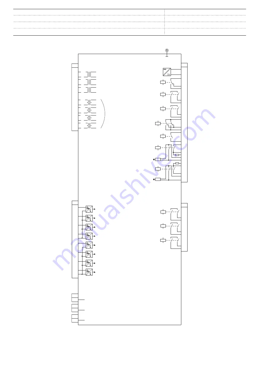
Figure 9.
Terminal diagram for application configuration B with CT and VT inputs
Substation Merging Unit
1MRS758420 B
SMU615
Product version: 1.0
26
ABB


