REM 543 Protection,
Monitoring and Control
Page 19
Technical Reference Manual
Part 1, General
ABB Network Partner
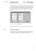
Interlocking LED texts can also be defined in the same alarm view, but the interlocking
LED colours cannot be changed. An interlocking LED has two special modes, the nor-
mal state of the LED being inactive. The first mode, i.e. a yellow steady lit LED, visual-
izes an interlocking action (operation failed due to interlocking), whereas the second
mode, a red blinking LED, indicates that the interlocking bypass mode (control test
mode) is on.
Fig. 4.1.2.2.-2. Alarm channel configuration.
For more information about the use of the editor, refer to the Relay Mimic Editor man-
ual.
4.1.2.3.
LON network configuration
The LON Network Tool is used for binding network variables between RED 500 pro-
tection terminals. Typically, LON is used for transferring status data between the protec-
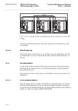
tion terminals for interlocking sequences running in each unit, see figure below.


