REM 543 Protection,
Monitoring and Control
Page 31
Technical Reference Manual
Part 1, General
ABB Network Partner
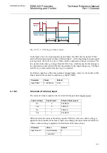
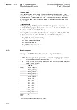
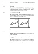
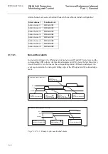
Fig. 4.1.6.1.-1. Filtering of a binary input.
In the figure above, the input signal is named ’Input’, the filter timer is named ’Filter’
and the filtered input signal is named 'Filtered Input’ . At the beginning the input signal
is at high state, the short low state is filtered and no input status change is detected. The
low state from the time t
0
is longer than the filter time, which means that the change in
the input status is detected and the time tag attached to the input change is t
0
. The high
state from t
1
is detected and the time tag t
1
is attached.
Each binary input has a filter time parameter Input # filter, where # is the number of the
binary input of the module in question (e.g. Input 1 filter).
4.1.6.2.
Inversion of a binary input
The status of a binary input can be inverted with the parameter Input # invert.:
When inverted, the status of the binary input is TRUE (1) when no control voltage is
applied to the terminals of the binary input. Accordingly, the input status is FALSE (0)
when a control voltage is applied to the terminals of the binary input.
Parameter
Values
Default
Input # filter
1....65535 ms
5 ms
t
0
t
1
dipo
Filter Time
Filtered Input
Input
Filter Time
Control voltage
Input # invert.
Status of binary input
No
0
FALSE (0)
Yes
0
TRUE (1)
No
1
TRUE (1)
Yes
1
FALSE (0)
Parameter
Values
Default
Input # invert.
0 (not inverted)
0
1 (inverted)

