REM 543 Protection,
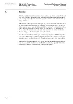
Monitoring and Control
Page 59
Technical Reference Manual
Part 1, General
ABB Network Partner
6.3.
Software configuration
Each REM 543 machine terminal allows different software configurations that are
based on application-specific libraries. When selecting the right software configuration,
the following items should be determined:
•
protection functions to be incorporated in the machine terminal
•
measurement functions to be incorporated in the machine terminal
•
control functions to be incorporated in the machine terminal
•
condition monitoring functions to be incorporated in the machine terminal
•
communication protocols needed to be incorporated in the machine terminal
•
standard library to be incorporated in the machine terminal
•
languages used on the MMI
Please consult your relay supplier for further information regarding available applica-
tion libraries and functions for REM 543 machine terminals.
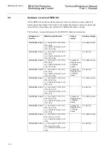
1MRS090216-AAB
I
n
= 1 A/5 A (CT1, CT2, CT3,
CT4, CT5, CT6, CT7)
U
n
= 100/110/115/120 V (VT1,
VT2)
8 inputs for
Rogowski coil
or voltage
divider
110...240 V ac/dc
1MRS090216-CAB
I
n
= 1 A/5 A (CT1, CT2, CT3,
CT4, CT5, CT6, CT7)
U
n
= 100/110/115/120 V (VT1,
VT2)
8 inputs for
Rogowski coil
or voltage
divider
24...60 V dc
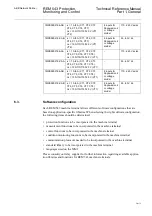
1MRS090218-AAA
I
n
= 1 A/5 A (CT1, CT2, CT3,
CT4, CT5, CT6, CT7, CT8)
U
n
= 100/110/115/120 V (VT1)
-
110...240 V ac/dc
1MRS090218-CAA
I
n
= 1 A/5 A (CT1, CT2, CT3,
CT4, CT5, CT6, CT7, CT8)
U
n
= 100/110/115/120 V (VT1)
-
24...60 V dc
1MRS090218-AAB
I
n
= 1 A/5 A (CT1, CT2, CT3,
CT4, CT5, CT6, CT7, CT8)
U
n
= 100/110/115/120 V (VT1)
8 inputs for
Rogowski coil
or voltage
divider
110...240 V ac/dc
1MRS090218-CAB
I
n
= 1 A/5 A (CT1, CT2, CT3,
CT4, CT5, CT6, CT7, CT8)
U
n
= 100/110/115/120 V (VT1)
8 inputs for
Rogowski coil
or voltage
divider
24...60 V dc

