A B
c
R
TD
/P
TC
1
R
TD
4/P
TC
2
E
xt
ern
al
trig
ge
rin
g
of
C
B
FA
IL
E
xt
ern
al
re
sta
rt
dis
ab
le
R
E
S
TA
R
T
D
IS
A
B
LE
R
es
ta
rt
dis
ab
le
*
R
est
art
dis
ab
le
sig
na
lf
ro
m
49
**
R
est
art
dis
ab
le
sig
na
lf
ro
m
66
TR
IP
49
/3
8-2
E
m
erg
en
cy
Sta
rt
E
m
erg
en
cy
Sta
rt
49
/3
8-1
M
oto
rst
art
up
46
R
E
m
erg
en
cy
Sta
rt
**
R
est
art
dis
ab
le
66
P
IC
K
U
P
46
P
IC
K
U
P
P
IC
K
U
P
P
IC
K
U
P
51
N
37
50
P
Sp
ee
d
sw
itch
/b
lo
cki
ng
(4
8/1
4
P
IC
K
U
P
)(4
8/1
4
TD
LY
)
/(4
8/1
4)
2
*R
est
art
dis
ab
le
49
E
m
erg
en
cy
Sta
rt
TR
IP
TR
IP
TR
IP
TR
IP
TR
IP
TR
IP
TR
IP
TR
IP
TR
IP
S
elf-s
up
erv
isio
n
3
4
5
6
7
8
9
10
11
12
13
14
15
16
17
18
19
cs
cs
c
T
21
22
23
24
= Factory default
1
2
3
5
6
7
8
9
10
11
12
13
14
16
17
18
19
15
4
1
2
3
5
6
7
8
9
10
11
12
13
14
16
17
18
19
15
4
1
2
3
5
6
7
8
9
10
11
12
13
14
16
17
18
19
15
4
1
2
3
5
6
7
8
9
10
11
12
13
14
16
17
18
19
15
4
1
2
3
5
6
7
8
9
10
11
12
13
14
16
17
18
19
15
4
8
9
10
11
12
13
8
9
10
11
12
13
8
9
10
11
12
13
8
9
10
11
12
13
8
9
10
11
12
13
1
2
3
4
5
6
7
14
1
2
3
4
5
6
7
14
1
2
3
4
5
6
7
14
1
2
3
4
5
6
7
14
1
2
3
4
5
6
7
14
Indications Cleared O
utput cont
act
s unlatched
M
em
orized values cleared
Setting group selection
Ti
m
e s
yn
c.
Ex
ternal
T
riggering
TR
IP
EXT
ALAR
M
ALAR
M
M
O
TO
R
S
T
Blocking
Blocking
Blocking
Blocking
W
arnin
g
IRF
SGF1...SGF5
SGL1...SGL8
A060571
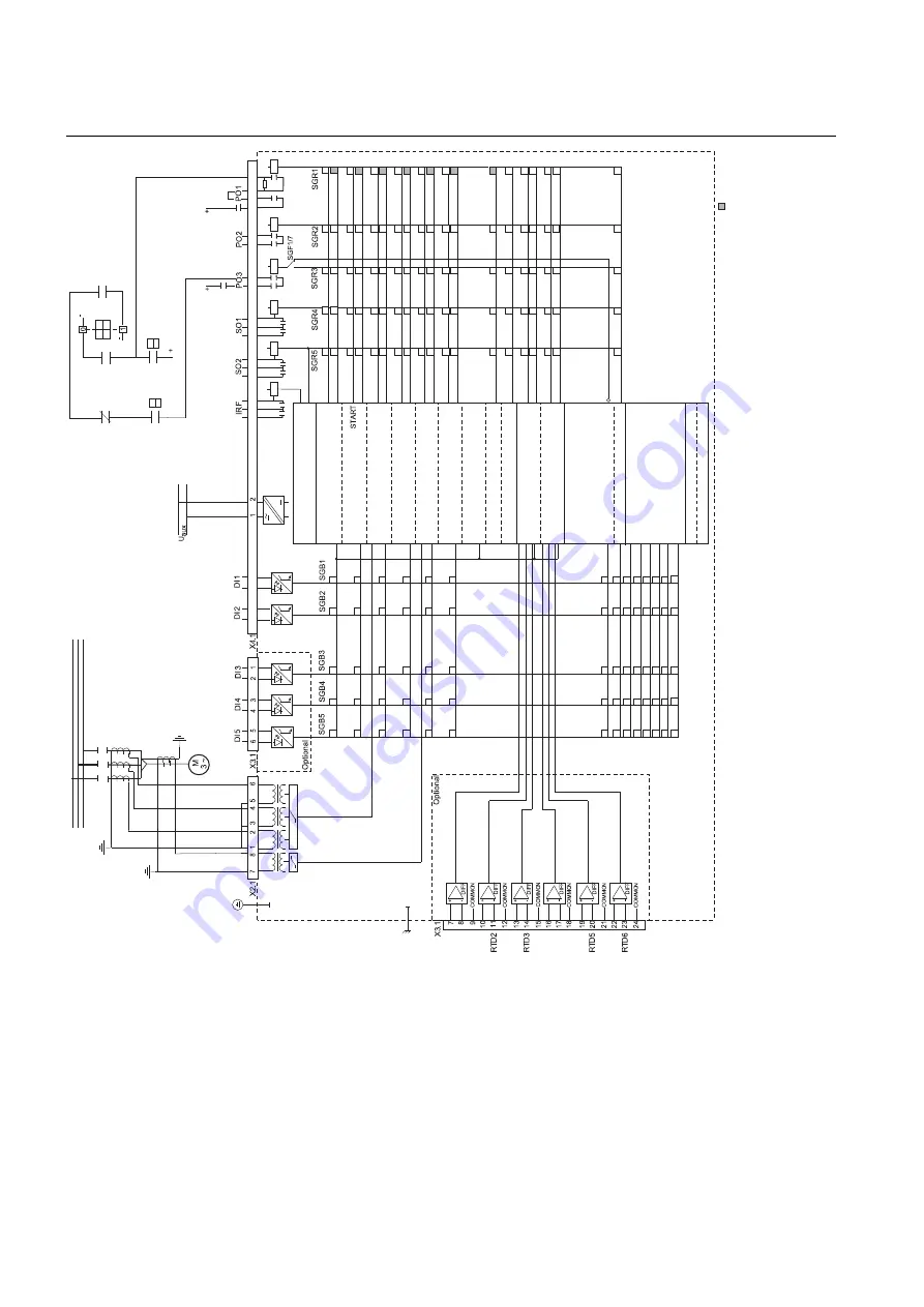
Fig. 4.2.-1
Connection diagram, example 1
16
REM 610
REM 610
Motor Protection Relay
Technical Reference Manual - ANSI Version
1MRS755537
Summary of Contents for REM 610
Page 1: ...Motor Protection Relay REM 610 REM 610 Technical Reference Manual ANSI Version ...
Page 2: ......
Page 6: ...6 ...
Page 8: ...8 ...
Page 12: ...12 ...
Page 124: ...124 ...
Page 144: ...144 ...
Page 154: ...154 ...
Page 157: ......


