118
Thermal phase overload protection
(THOL)
&KDSWHU
&XUUHQW
7KHUPDOSKDVHRYHUORDGSURW2/
$SSOLFDWLRQ
The thermal phase overload protection function is intended for single- and two-phase
systems. The function measures one phase current.
When the load currents exceed the permitted continuous current there is a risk that the
conductor or the insulation will be subject to permanent damage due to overheating.
Even moderate overloads under long time give appreciable temperature increase. For
example, a current of 1.2 times rated load current gives a temperature rise of 1.2 x 1.2
= 1.44 times rated value.
The temperature rise as a function of time for a fixed load is determined by the so called
thermal time constant
τ
of the element. Moderate overloads are normally not detected
by current or impedance measuring relays. A current thermal overload protection can
prevent damage caused by excessive temperature increase due to moderate or heavy
current overloads.
For overhead lines, the ambient temperature will normally vary considerably. Since the
temperature of the element is the sum of the ambient temperature and the temperature
rise, the thermal protection for heavily loaded lines should be provided with compensa-
tion for the ambient temperature. The heating effect of radiant power from the sun can
also be appreciable in some areas.
)XQFWLRQDOLW\
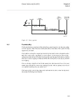
The current measuring element in one of the signal processors continuously measures
the RMS value of the conductor current.
The function includes a memory that is continuously updated with the calculated heat
content of the line based on the RMS value of the line current and the ambient temper-
ature. The function has two settable operating levels for temperature, one intended for
alarm and one intended for tripping. For the tripping function a reset hysteresis is in-
cluded that can be set between 5 and 30°C while for the alarm function it is fixed at 5°C
hysteresis.
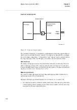
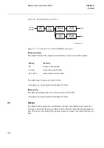
The function for ambient temperature compensation is connected to a mA transducer
input. The upper and lower value for the input range can be set between -25 and +25
mA and corresponding temperature between -1000 and + 1000°C. If transducer for am-
bient temperature is not available, the function uses a +20°C reference value instead.
This value will also be used if a fault is detected in the transducer circuits or mA input
module.
Summary of Contents for REO 517
Page 10: ... RQWHQWV ...
Page 16: ...6 Introduction to the application manual KDSWHU QWURGXFWLRQ ...
Page 64: ...54 Blocking of signals during test KDSWHU RPPRQ IXQFWLRQV ...
Page 88: ...78 Scheme communication logic ZCOM KDSWHU LQH LPSHGDQFH ...
Page 146: ...136 Unbalance protection for capacitor banks TOCC KDSWHU XUUHQW ...
Page 166: ...156 Dead line detection DLD KDSWHU 3RZHU V VWHP VXSHUYLVLRQ ...
Page 378: ...368 Monitoring of DC analog measurements KDSWHU 0RQLWRULQJ ...
Page 384: ...374 Pulse counter logic PC KDSWHU 0HWHULQJ ...
Page 412: ...402 Serial communication modules SCM KDSWHU DWD FRPPXQLFDWLRQ ...
Page 440: ...430 LED indication module KDSWHU DUGZDUH PRGXOHV ...


