133
Unbalance protection for capacitor banks
(TOCC)
&KDSWHU
&XUUHQW
8QEDODQFHSURWHFWLRQIRUFDSDFLWRUEDQNV72&&
$SSOLFDWLRQ
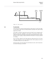
The unbalance protection for capacitor banks works independent of number of phases
in the system since it measures the unbalance currents between two normally balanced
parts.
Capacitor banks are made up of individual units which are connected in series and par-
allel. Each unit contains a number of series and parallel connected elements. The indi-
vidual elements in a capacitor can be separately fused.
If one element is short-circuited or disconnected by its fuse the rest of the elements can
continue to operate. However, the load on the healthy elements will increase. When a
certain number of elements are out of service, the load on the remaining elements be-
comes so high that the remaining elements will quickly be destroyed.The purpose of the
unbalance protection is to detect the damage and disconnect the capacitor bank from the
network before the healthy units are overloaded.
The protection is connected to a current transformer which measures the current flow-
ing between two normally balanced parts of the capacitor battery. Under normal condi-
tions, only an insignificant fundamental frequency current flows in the interconnection.
A low set current stage gives alarm when elements are damaged and current flows in
the interconnection. The trip stage is set to disconnect the battery before healthy ele-
ments become overloaded and quickly damaged.
)XQFWLRQDOLW\
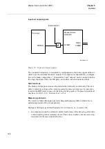
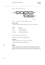
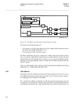
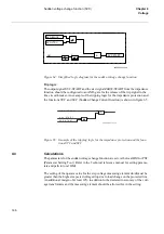
The current measuring element continuously measures the unbalance current and com-
pares it to the set operate value for the two current stages. A recursive Fourier filter en-
sures immunity to disturbances and harmonic currents. The output relay for the low
current (alarm) stage operates if the current becomes higher than the set operate value
ILow during a time exceeding the set time delay tLow. If the current becomes higher
than the set operate value IHigh during a time exceeding the set delay tHigh, the output
relay for the high current stage operates.
The simplified logic diagram for the unbalance protection is shown in figure 59:
Summary of Contents for REO 517
Page 10: ... RQWHQWV ...
Page 16: ...6 Introduction to the application manual KDSWHU QWURGXFWLRQ ...
Page 64: ...54 Blocking of signals during test KDSWHU RPPRQ IXQFWLRQV ...
Page 88: ...78 Scheme communication logic ZCOM KDSWHU LQH LPSHGDQFH ...
Page 146: ...136 Unbalance protection for capacitor banks TOCC KDSWHU XUUHQW ...
Page 166: ...156 Dead line detection DLD KDSWHU 3RZHU V VWHP VXSHUYLVLRQ ...
Page 378: ...368 Monitoring of DC analog measurements KDSWHU 0RQLWRULQJ ...
Page 384: ...374 Pulse counter logic PC KDSWHU 0HWHULQJ ...
Page 412: ...402 Serial communication modules SCM KDSWHU DWD FRPPXQLFDWLRQ ...
Page 440: ...430 LED indication module KDSWHU DUGZDUH PRGXOHV ...


