155
Dead line detection (DLD)
&KDSWHU
3RZHUV\VWHPVXSHUYLVLRQ
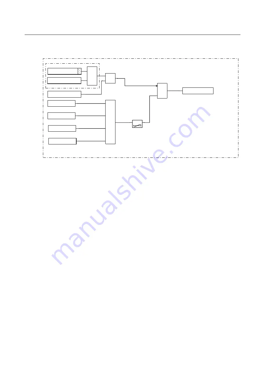
)LJXUH 6LPSOLILHGORJLFGLDJUDPIRUWKH'/'IXQFWLRQ
An external signal, which is connected to the input DLD-BLOCK, blocks the function.
The function is also blocked by the setting Block-DLD=Yes if the terminal is in test
mode.
&DOFXODWLRQV
The parameters for the dead line detection function are set via the local HMI or PST
(Parameter Setting Tool). Refer to the Technical reference manual for setting parame-
ters and path in local HMI.
Due to technical reasons settings are shown under Setting/Group n/DeadLineDet de-
spite that they have no influence on the function. On the local HMI the parameters for
the dead line detection function are set under the two menus for TUV and Z(n)RW.
Set the operate voltage UPE< at least 15% lower than the lowest phase-to-neutral volt-
age with normal operations.
Set the operate current IMinop at least 15% lower than the lowest phase-to-neutral cur-
rent with normal operations.
The settings must be coordinated with TUV and Z(n)RW since UPE< and IMinop are
common.
DLD-START
Z3RW-STIML2
TUV-STUL1N
Block DLD=Yes
TEST-ACTIVE
DLD-BLOCK
≥
1
Z3RW-STIML1
&
t
t
TEST
&
&
TUV-STUL2N
en02000559.vsd
Summary of Contents for REO 517
Page 10: ... RQWHQWV ...
Page 16: ...6 Introduction to the application manual KDSWHU QWURGXFWLRQ ...
Page 64: ...54 Blocking of signals during test KDSWHU RPPRQ IXQFWLRQV ...
Page 88: ...78 Scheme communication logic ZCOM KDSWHU LQH LPSHGDQFH ...
Page 146: ...136 Unbalance protection for capacitor banks TOCC KDSWHU XUUHQW ...
Page 166: ...156 Dead line detection DLD KDSWHU 3RZHU V VWHP VXSHUYLVLRQ ...
Page 378: ...368 Monitoring of DC analog measurements KDSWHU 0RQLWRULQJ ...
Page 384: ...374 Pulse counter logic PC KDSWHU 0HWHULQJ ...
Page 412: ...402 Serial communication modules SCM KDSWHU DWD FRPPXQLFDWLRQ ...
Page 440: ...430 LED indication module KDSWHU DUGZDUH PRGXOHV ...


