226
Apparatus control
&KDSWHU
&RQWURO
)LJXUH&RQQHFWLRQVEHWZHHQD6LQJOH&PG)XQFEORFNFRQWUROOHGIURPWKHORFDO
+0,DQGWKHDSSDUDWXVFRQWUROPRGXOHV
,QWHUORFNLQJ
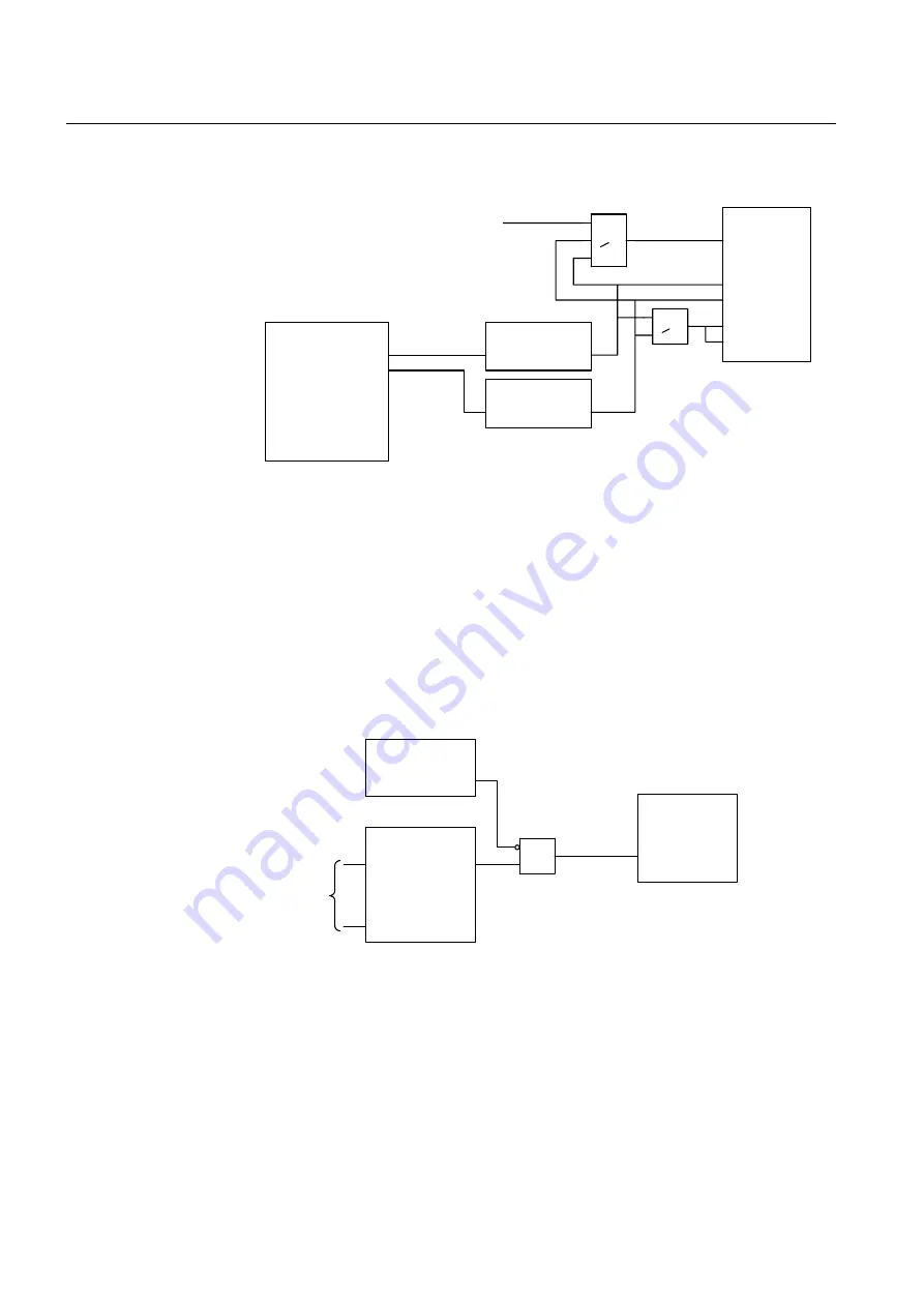
Figure 107 shows the connection between an interlocking module and apparatus control
modules. The input is activated when the apparatus is interlocked. The interlocking in-
formation within the control terminal are taken from the binary input boards. Informa-
tion from other bays are transferred over the station bus. The section 5.8.3 "Reservation
function" describes the method for transferring these data.
)LJXUH&RQQHFWLRQRIDQLQWHUORFNLQJPRGXOHWRDSSDUDWXVFRQWUROPRGXOHV
SingleCmdFunc
OUT1
OUT2
OUT3
OUT4
.
.
OUT16
Pulse
INPUT OUT
Pulse
INPUT OUT
Apparatus 1 open
Apparatus 1 close
>1
>1
Apparatus 1
LOCAL
From BAYCON
Defined as pulse outputs
Pulse length = 1 s
99000338.vsd
COMCON
LOCAL
L_SEL_O
L_SEL_C
L_OPEN
L_CLOSE
COMCON
OVERRIDE
Interlocking
ITL
.
.
.
Signals from
binary input
boards and
from other
bays
&
SWICON
INT_LOCK
Interlocked
99000339.vsd
Summary of Contents for REO 517
Page 10: ... RQWHQWV ...
Page 16: ...6 Introduction to the application manual KDSWHU QWURGXFWLRQ ...
Page 64: ...54 Blocking of signals during test KDSWHU RPPRQ IXQFWLRQV ...
Page 88: ...78 Scheme communication logic ZCOM KDSWHU LQH LPSHGDQFH ...
Page 146: ...136 Unbalance protection for capacitor banks TOCC KDSWHU XUUHQW ...
Page 166: ...156 Dead line detection DLD KDSWHU 3RZHU V VWHP VXSHUYLVLRQ ...
Page 378: ...368 Monitoring of DC analog measurements KDSWHU 0RQLWRULQJ ...
Page 384: ...374 Pulse counter logic PC KDSWHU 0HWHULQJ ...
Page 412: ...402 Serial communication modules SCM KDSWHU DWD FRPPXQLFDWLRQ ...
Page 440: ...430 LED indication module KDSWHU DUGZDUH PRGXOHV ...


