235
Apparatus control
&KDSWHU
&RQWURO
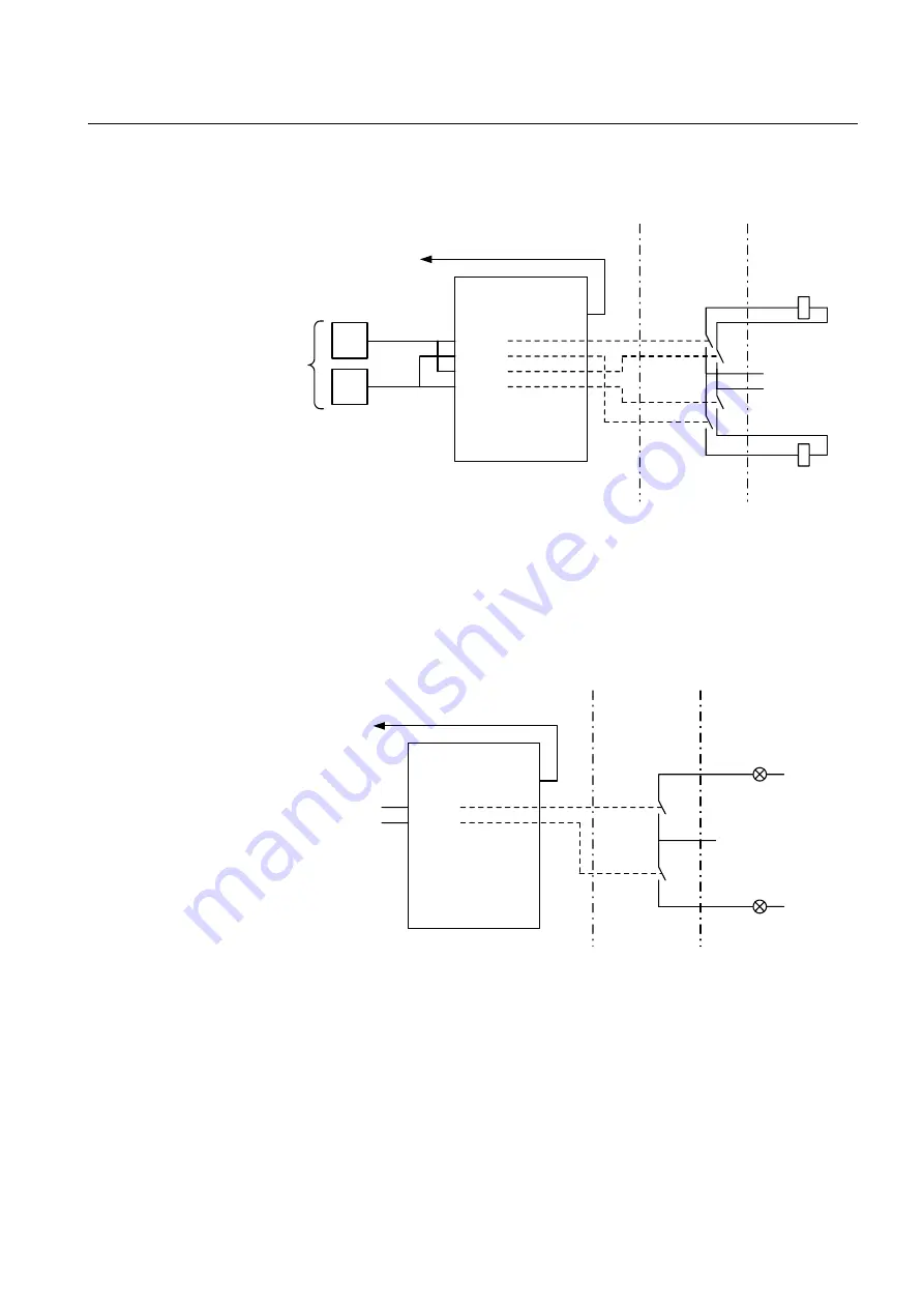
)LJXUH'RXEOHSROHFRPPDQGRXWSXWVZLWKVXSHUYLVLRQ
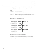
Figure 118 shows the configuration of single outputs used for purposes other than op-
erating high-voltage apparatuses. Here the ERROR signal is connected to an event
function block for alarming or as a condition for another application. The security is
limited compared to the solutions above - with two contacts in series.
)LJXUH6LQJOHRXWSXWFRPPDQGV
I/O-module
ERROR
BO1
BO2
BO3
BO4
BO24
.
.
.
&
&
OPEN
CLOSE
From
SWI-
CON
To BLKCONL
Application software
BO.01
BO.02
BO.03
BO.04
Binary
Output
Module
Switchyard
Close
coil
-
Open
coil
+
99000349.vsd
I/O-module
ERROR
BO1
BO2
BO3
BO4
BO24
.
.
.
For alarming
Application software
BO.01
BO.02
Binary
Output
Module
Switchyard/
control room
-
+
99000350.vsd
-
On/Off
On/Off
Summary of Contents for REO 517
Page 10: ... RQWHQWV ...
Page 16: ...6 Introduction to the application manual KDSWHU QWURGXFWLRQ ...
Page 64: ...54 Blocking of signals during test KDSWHU RPPRQ IXQFWLRQV ...
Page 88: ...78 Scheme communication logic ZCOM KDSWHU LQH LPSHGDQFH ...
Page 146: ...136 Unbalance protection for capacitor banks TOCC KDSWHU XUUHQW ...
Page 166: ...156 Dead line detection DLD KDSWHU 3RZHU V VWHP VXSHUYLVLRQ ...
Page 378: ...368 Monitoring of DC analog measurements KDSWHU 0RQLWRULQJ ...
Page 384: ...374 Pulse counter logic PC KDSWHU 0HWHULQJ ...
Page 412: ...402 Serial communication modules SCM KDSWHU DWD FRPPXQLFDWLRQ ...
Page 440: ...430 LED indication module KDSWHU DUGZDUH PRGXOHV ...


