263
Interlocking
&KDSWHU
&RQWURO
,QWHUORFNLQJIRUEXVVHFWLRQGLVFRQQHFWRU
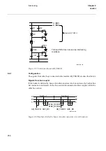
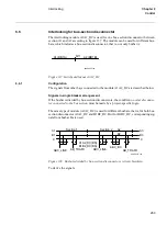
The interlocking module A1A2_DC is used for one bus-section disconnector between
section A1 and A2 according to figure 137. The module can be used for different bus-
bars, which includes a bus-section disconnector, that is, not only busbar A.
)LJXUH6ZLWFK\DUGOD\RXW$$B'&
&RQILJXUDWLRQ
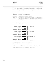
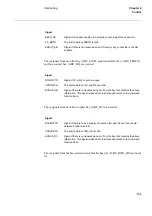
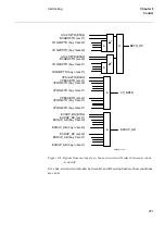
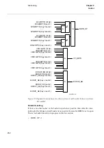
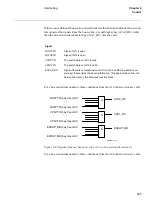
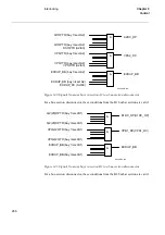
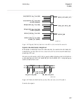
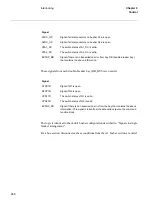
The signals from other bays connected to the module A1A2_DC are described below.
6LJQDOVLQVLQJOHEUHDNHUDUUDQJHPHQW
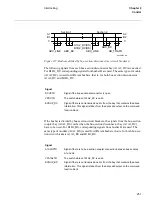
If the busbar is divided by bus-section disconnectors, the condition
QRRWKHUGLVFRQQHF
WRUFRQQHFWHGWRWKHEXVVHFWLRQ
must be made by a project-specific logic.
The same type of module (A1A2_DC) is used for different busbars, that is, for both bus-
section disconnector A1A2_DC and B1B2_DC. But for B1B2_DC, corresponding sig-
nals from busbar B are used.
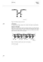
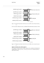
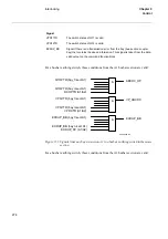
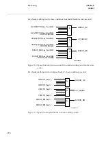
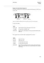
)LJXUH%XVEDUVGLYLGHGE\EXVVHFWLRQGLVFRQQHFWRUVFLUFXLWEUHDNHUV
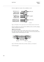
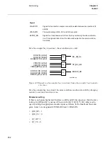
To derive the signals:
99000357.vsd
A1 (BB1A)
A2 (BB1B)
Q11
Section 1
Section 2
A1A2_DC(BS)
B1B2_DC(BS)
ABC_LINE
ABC_BC
ABC_LINE
A1
B1
C
C
B3
A3
99000373.vsd
AB_TRAFO
AB_TRAFO
A2
B2
Summary of Contents for REO 517
Page 10: ... RQWHQWV ...
Page 16: ...6 Introduction to the application manual KDSWHU QWURGXFWLRQ ...
Page 64: ...54 Blocking of signals during test KDSWHU RPPRQ IXQFWLRQV ...
Page 88: ...78 Scheme communication logic ZCOM KDSWHU LQH LPSHGDQFH ...
Page 146: ...136 Unbalance protection for capacitor banks TOCC KDSWHU XUUHQW ...
Page 166: ...156 Dead line detection DLD KDSWHU 3RZHU V VWHP VXSHUYLVLRQ ...
Page 378: ...368 Monitoring of DC analog measurements KDSWHU 0RQLWRULQJ ...
Page 384: ...374 Pulse counter logic PC KDSWHU 0HWHULQJ ...
Page 412: ...402 Serial communication modules SCM KDSWHU DWD FRPPXQLFDWLRQ ...
Page 440: ...430 LED indication module KDSWHU DUGZDUH PRGXOHV ...


