31
I/O system configurator (IOP)
&KDSWHU
&RPPRQIXQFWLRQV
If the user-entered configuration does not match the actual configuration in the termi-
nal, an error output is activated on the function block, which can be treated as an event
or alarm.
,2SRVLWLRQ
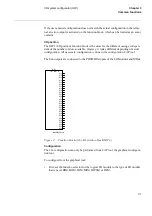
The IOP1 (I/O position) function block is the same for the different casings, indepen-
dent of the number of slots available. Anyway, it looks different depending of actual
configuration. All necessary configuration is done in the configuration CAP tool.
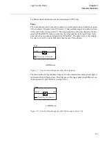
The Snn outputs are connected to the POSITION inputs of the I/O Modules and MIMs.
)LJXUH )XQFWLRQEORFNRIWKH,2SRVLWLRQEORFN,23
&RQILJXUDWLRQ
The I/O-configuration can only be performed from CAP tool, the graphical configura-
tion tool.
To configure from the graphical tool:
•
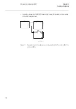
First, set the function selector for the logical I/O module to the type of I/O module
that is used, BIM, BOM, IOM, MIM, IOPSM or DCM.
xx00000238.vsd
IOP1-
,2326,7,21
S11
S12
S13
S14
S15
S16
S17
S18
S19
S20
S21
S22
S23
S24
S25
S26
S27
S28
S29
S30
S32
S33
S34
S35
S36
S37
S39
Summary of Contents for REO 517
Page 10: ... RQWHQWV ...
Page 16: ...6 Introduction to the application manual KDSWHU QWURGXFWLRQ ...
Page 64: ...54 Blocking of signals during test KDSWHU RPPRQ IXQFWLRQV ...
Page 88: ...78 Scheme communication logic ZCOM KDSWHU LQH LPSHGDQFH ...
Page 146: ...136 Unbalance protection for capacitor banks TOCC KDSWHU XUUHQW ...
Page 166: ...156 Dead line detection DLD KDSWHU 3RZHU V VWHP VXSHUYLVLRQ ...
Page 378: ...368 Monitoring of DC analog measurements KDSWHU 0RQLWRULQJ ...
Page 384: ...374 Pulse counter logic PC KDSWHU 0HWHULQJ ...
Page 412: ...402 Serial communication modules SCM KDSWHU DWD FRPPXQLFDWLRQ ...
Page 440: ...430 LED indication module KDSWHU DUGZDUH PRGXOHV ...


