32
I/O system configurator (IOP)
&KDSWHU
&RPPRQIXQFWLRQV
•
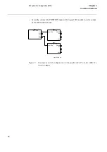
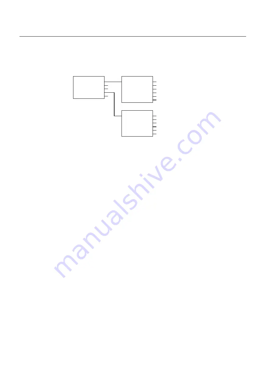
Secondly, connect the POSITION input of the logical I/O module to a slot output
of the IOP function block.
)LJXUH ([DPSOHRIDQ,2FRQILJXUDWLRQLQWKHJUDSKLFDO&$3WRROIRUD5([[[
ZLWKWZR%,0V
,202'8/(
IO01-
POSITION
ERROR
BI1
.
.
.
BI16
,202'8/(
IO02-
POSITION
ERROR
BI1
.
.
.
BI16
IOP1-
,2326,7,21
S11
S13
S15
S17
S19
en01000142.vsd
Summary of Contents for REO 517
Page 10: ... RQWHQWV ...
Page 16: ...6 Introduction to the application manual KDSWHU QWURGXFWLRQ ...
Page 64: ...54 Blocking of signals during test KDSWHU RPPRQ IXQFWLRQV ...
Page 88: ...78 Scheme communication logic ZCOM KDSWHU LQH LPSHGDQFH ...
Page 146: ...136 Unbalance protection for capacitor banks TOCC KDSWHU XUUHQW ...
Page 166: ...156 Dead line detection DLD KDSWHU 3RZHU V VWHP VXSHUYLVLRQ ...
Page 378: ...368 Monitoring of DC analog measurements KDSWHU 0RQLWRULQJ ...
Page 384: ...374 Pulse counter logic PC KDSWHU 0HWHULQJ ...
Page 412: ...402 Serial communication modules SCM KDSWHU DWD FRPPXQLFDWLRQ ...
Page 440: ...430 LED indication module KDSWHU DUGZDUH PRGXOHV ...


