411
A/D-conversion module (ADM)
&KDSWHU
+DUGZDUHPRGXOHV
$'FRQYHUVLRQPRGXOH$'0
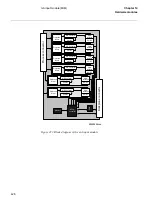
The incoming signals from the intermediate current transformers are adapted to the
electronic voltage level with shunts. To gain dynamic range for the current inputs, two
shunts with separate A/D channels are used for each input current. By that a 16-bit dy-
namic range is obtained with a 12 bits A/D converter.
The next step in the signal flow is the analog filter of the first order, with a cut-off fre-
quency of 500 Hz. This filter is used to avoid aliasing problems.
The A/D converter has a 12-bit resolution. It samples each input signal (5 voltages and
2x5 currents) with a sampling frequency of 2 kHz.
Before the A/D-converted signals are transmitted to the signal processing module, the
signals are band-pass filtered and down-sampled to 1 kHz in a digital signal processor
(DSP).
The filter in the DSP is a numerical filter with a cut-off frequency of 250 Hz.
The transmission of data between the A/D-conversion module and the signal processing
module is done on a supervised serial link of RS485 type. This transmission is per-
formed once every millisecond and contains information about all incoming analog sig-
nals.
Summary of Contents for REO 517
Page 10: ... RQWHQWV ...
Page 16: ...6 Introduction to the application manual KDSWHU QWURGXFWLRQ ...
Page 64: ...54 Blocking of signals during test KDSWHU RPPRQ IXQFWLRQV ...
Page 88: ...78 Scheme communication logic ZCOM KDSWHU LQH LPSHGDQFH ...
Page 146: ...136 Unbalance protection for capacitor banks TOCC KDSWHU XUUHQW ...
Page 166: ...156 Dead line detection DLD KDSWHU 3RZHU V VWHP VXSHUYLVLRQ ...
Page 378: ...368 Monitoring of DC analog measurements KDSWHU 0RQLWRULQJ ...
Page 384: ...374 Pulse counter logic PC KDSWHU 0HWHULQJ ...
Page 412: ...402 Serial communication modules SCM KDSWHU DWD FRPPXQLFDWLRQ ...
Page 440: ...430 LED indication module KDSWHU DUGZDUH PRGXOHV ...


