background image

429

LED indication module

&KDSWHU

+DUGZDUHPRGXOHV

/('LQGLFDWLRQPRGXOH

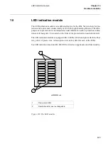
The LED indication module is an additional feature for the REx 5xx terminals for pro-
tection and control and consists totally of 18 LEDs (Light Emitting Diodes). The main 
purpose is to present on site an immediate visual information such as protection indica-
tions or alarm signals. It is located on the front of the protection and control terminals. 

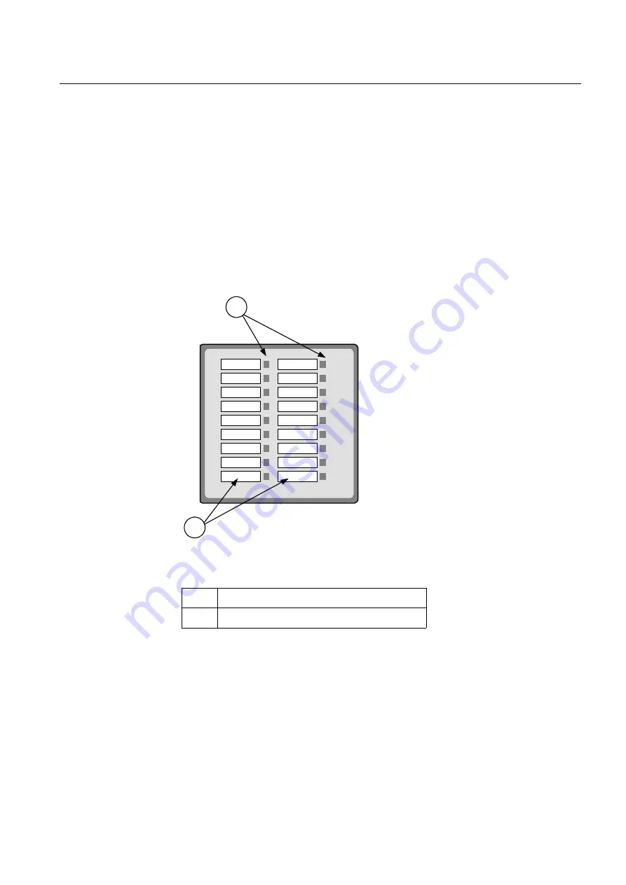
The LED indication module is equipped with 18 LEDs, which can light or flash in either 
red, yellow or green color. A description text can be added for each of the LEDs.

See LED indication function (HL, HLED) for details on application and functionality.

)LJXUH7KH/('PRGXOH

1

Three-color LEDs

2

Descriptive label, user exchangeable

xx00000406.vsd

1

2

Summary of Contents for REO 517

Page 1: ... Copyright 2002 ABB All rights reserved SSOLFDWLRQ PDQXDO REO 517 2 4 Multi functional terminals for railway application ERXW WKLV PDQXDO Document No 1MRK 506 132 UEN Issued November 2002 Revision ...

Page 2: ...8 6 17 1 62 25 7 352 8 7 6 5 37 21 1 6 127 72 0 72 67 7 0 17 2 8 5 17 3523 5 7 6 1 7 17 5 676 2 285 86720 56 2167 17 6 72 1685 7 7 285 352 8 76 5 9 23 72 7 7 67 7 12 2 67 1 5 6 6 5 68 7 7 6 3266 7 7 7 5 0 620 5 1 6 7 1 7 6 352 8 7 1 7 6 1 250 7 21 352 8 7 0DQXIDFWXUHU ABB Automation Technology Products AB Control Force Measurement Substation Automation SE 721 59 Västerås Sweden Telephone 46 0 21 3...

Page 3: ... 18 Hardware requirements 19 Terminal identification and base values 20 Application 20 Calculations 20 KDSWHU RPPRQ IXQFWLRQV Time synchronisation TIME 24 Application 24 Functionality 24 Calculations 24 Setting group selector GRP 26 Application 26 Functionality 26 Design 27 Setting lockout HMI 28 Application 28 Functionality 28 I O system configurator IOP 30 Application 30 Functionality 30 Logic f...

Page 4: ...tion 80 Functionality 80 Calculations 82 Time delayed phase and residual overcurrent protection TOC1 85 Application 85 Functionality 85 Calculations 87 Two step definite and inverse time delayed phase overcurrent protection TOC2 91 Application 91 Functionality 91 Calculations 94 Sudden current change function SCC 99 Application 99 Functionality 99 Calculations 101 Two step definite and inverse tim...

Page 5: ...ection TUV for two sections TUV1 138 Application 138 Design 138 Calculations 140 Inverse time delayed undervoltage protection TUV2 141 Application 141 Functionality 141 Calculations 142 Time delayed phase overvoltage protection TOV 143 Application 143 Functionality 143 Calculations 144 Sudden voltage change function SVC 145 Application 145 Functionality 145 Calculations 146 Line test function LITE...

Page 6: ...1 Application 181 Design 182 Calculations 183 Multiple command CM 184 Application 184 Design 184 Calculations 185 Apparatus control 186 Application 186 Functionality 187 Design 194 BAYCON 197 COMCON 201 SWICON 203 BLKCON 206 Configuration 206 Interlocking 236 Overview 236 Interlocking for line bay 242 Interlocking for bus coupler bay 249 Interlocking for transformer bay 255 Interlocking for bus se...

Page 7: ...ndication function HL HLED 294 Application 294 Functionality 294 Calculations 307 Disturbance report DRP 308 Application 308 Functionality 308 Calculations 313 Indications 318 Application 318 Functionality 318 Calculations 319 Disturbance recorder 320 Application 320 Functionality 320 Design 323 Calculations 324 Event recorder 326 Application 326 Functionality 326 Calculations 326 Fault locator FL...

Page 8: ...emote end data communication 376 Application 376 Design 377 Optical fibre communication module 379 Application 379 Design 380 Galvanic data communication module 382 Application 382 Design 383 Short range galvanic module 384 Application 384 Short range optical fibre module 386 Application 386 G 703 module 388 Application 388 Carrier module 389 Application 389 Design 389 Serial communication 391 App...

Page 9: ...form configuration 405 1 1x19 platform 408 3 4x19 platform 408 1 2x19 platform 409 Transformer input module TRM 410 A D conversion module ADM 411 Main processing module MPM 413 Signal processing module SPM 415 Input Output modules 416 General 416 Binary input module BIM 418 Binary output module BOM 419 Binary I O module IOM 421 Power supply module PSM 423 mA input module MIM 425 Human machine inte...

Page 10: ... RQWHQWV ...

Page 11: ...1 About this chapter KDSWHU QWURGXFWLRQ KDSWHU QWURGXFWLRQ ERXW WKLV FKDSWHU This chapter introduces you to the manual as such ...

Page 12: ...ference during the engineering phase installation and commissioning phase and during the normal service phase 7KH 2SHUDWRU V 0DQXDO 20 contains instructions on how to operate the protection terminal during normal service after commissioning and before periodic maintenance tests The operator s manual could be used to find out how to handle disturbances or how to view calculated and measured network...

Page 13: ...ion 5HODWHG GRFXPHQWV 5HYLVLRQ QRWHV FURQ PV DQG DEEUHYLDWLRQV RFXPHQWV UHODWHG WR 5 2 GHQWLW QXPEHU Operator s manual 1MRK 506 134 UEN Installation and commissioning manual 1MRK 506 133 UEN Technical reference manual 1MRK 506 131 UEN Application manual 1MRK 506 132 UEN Technical overview brochure 1MRK 506 135 BEN 5HYLVLRQ HVFULSWLRQ 2 4 00 First revision 1 Controller Area Network ISO standard ISO...

Page 14: ...al description for digital lines used by local telephone companies Can be transported over balanced and un balanced lines Standard for pulse code modulation of analog signals on digital lines 6 Gas Insulated Switchgear A serial master slave protocol for point to point communication A network technology standard that provides 100 Mbits s on twist ed pair or optical fiber cable 3 PCI Mezzanine Card ...

Page 15: ...ial master slave protocol for point to point communication 8 3 6 Process interface components that delivers measured voltage and current values 87 Coordinated Universal Time A coordinated time scale maintained by the Bureau International des Poids et Mesures BIPM which forms the basis of a coordinated dissemination of standard fre quencies and time signals 9 Same as RS449 A generic connector speci...

Page 16: ...6 Introduction to the application manual KDSWHU QWURGXFWLRQ ...

Page 17: ...7 About this chapter KDSWHU HQHUDO KDSWHU HQHUDO ERXW WKLV FKDSWHU This chapter describes the terminal in general ...

Page 18: ...breaker failure protection Wide range of control functionality available Complete autoreclosing function Syncrocheck with phasing and energising check Extensive disturbance report with 10 most recent disturbances recorded FIFO 40 seconds disturbance recorder 18 LEDs for extended indication capabilities Versatile local human machine interface HMI Simultaneous dual protocol serial communication faci...

Page 19: ...lectric power systems in single or two phase high impedance or solidly earthed railway systems which is running at 16 2 3 50 or 60 Hz It is suitable for the protection of lines where the load varies within wide limits due to train operation The terminal may also be used to provide backup protection for power transformers bus bars etc ...

Page 20: ...ulfill the strin gent EMC requirements All serial data communication is via optical connections to ensure immunity against disturbances An extensive library of protection control and monitoring functions is available This library of functions together with the flexible hardware design allows this terminal to be configured to each user s own specific requirements This wide application flexibil ity ...

Page 21: ...ge drop down to zero the secondary voltage should drop to less than 10 of the peak pre fault value before the short circuit within one cycle The protection terminal has an effective filter for this transient which gives secure and correct operation with CVTs XUUHQW WUDQVIRUPHUV ODVVLILFDWLRQ The performance of the REx 5xx terminal depends on the conditions and the quality of the current signals fe...

Page 22: ...rent The airgaps will also reduce the measuring accuracy in the non saturated region of operation Class TPZ according to IEC is a non remanence type CT The rated equivalent limiting secondary e m f Eal according to the IEC 60044 6 stan dard is used to specify the CT requirements for REx 5xx The requirements are also specified according to other standards RQGLWLRQV The requirements are a result of ...

Page 23: ...ult will exceed the cur rent for a three phase fault when the zero sequence impedance in the total fault loop is less than the positive sequence impedance When calculating the current transformer requirements maximum fault current should be used and therefore both fault types have to be considered DEOH UHVLVWDQFH DQG DGGLWLRQDO ORDG The current transformer saturation is directly affected by the vo...

Page 24: ...nd of zone 1 reach A Ipn The rated primary CT current A Isn The rated secondary CT current A IR The protection terminal rated current A RCT The secondary resistance of the CT Ω RL The resistance of the secondary cable and additional load Ω The loop resistance should be used for phase to earth faults and the phase resistance for three phase faults a This factor is a function of the network frequenc...

Page 25: ...15 Requirements KDSWHU HQHUDO LJXUH DFWRU D DV D IXQFWLRQ RI WKH IUHTXHQF DQG WKH WLPH FRQVWDQW LJXUH DFWRU N DV D IXQFWLRQ RI WKH IUHTXHQF DQG WKH WLPH FRQVWDQW 60 Hz 50 Hz 60 Hz 50 Hz ...

Page 26: ... 1 is specified by the secondary limiting e m f E2max The value of the E2max is approximately equal to Eal according to IEC 60044 6 Equation 3 The current transformers must have a secondary limiting e m f E2max that fulfills the following Equation 4 XUUHQW WUDQVIRUPHU DFFRUGLQJ WR ULWLVK 6WDQGDUG 6 A CT according to BS is often specified by the rated knee point e m f EkneeBS The val ue of the Ekne...

Page 27: ...fied knee point voltage UkneeANSI This is graphically defined from the excitation curve The knee point according to ANSI IEEE has normally a lower value than the knee point according to BS The rated equivalent limiting secondary e m f EalANSI for a CT specified according to ANSI IEEE can be estimated to Equation 9 The current transformers must have a knee point voltage UkneeANSI that fulfills the ...

Page 28: ...tation control system SCS For that pur pose connect the LON communication link to a LON Star Coupler via optical fibres The optical fibres are either glass or plastic with specification according to Hardware modules in the Technical reference manual A PC can be used as a station HMI The PC must be equipped with a communication card for LON e g Echelon PCLTA card To configure the nodes in a SCS the...

Page 29: ...IDFLQJ The PC shall comply with the following requirements the CAP tools must be available for communication to the front port one serial port COM available general PC requirements are defined by the used software tools Refer to the docu mentation of the software tools for further information ...

Page 30: ...tagging of Internal events Disturbance reports Events in a disturbance report Events transmitted to the SCS substation control system This implies that the internal clock is very important The clock can be synchronized see Time synchronization to achieve higher accuracy of the time tagging Without synchronization the internal clock is useful for comparisons among events within the REx 5xx terminal...

Page 31: ...g voltage UsSEC is Equation 13 The relay setting value UPE is given in percentage of the base voltage value Uxb as sociated to the voltage transformer input Ux where ISEC secondary rated current of the main CT IPRIM primary rated current of the main CT Is primary setting value of the current where USEC secondary rated voltage of the main VT UPRIM primary rated voltage of the main VT Us primary set...

Page 32: ...22 Terminal identification and base values KDSWHU HQHUDO Equation 14 The value of Uxb can be calculated as UPE UsSEC Uxb 100 Uxb Rated primary voltage VT ratio ...

Page 33: ...23 About this chapter KDSWHU RPPRQ IXQFWLRQV KDSWHU RPPRQ IXQFWLRQV ERXW WKLV FKDSWHU This chapter presents the common functions in the terminal ...

Page 34: ...cted to a binary input The minute pulse is used to fine tune already existing time in the terminals The REx 5xx terminal has its own internal clock with date hour minute second and millisecond It has a resolution of 1 ms The clock has a built in calendar that handles leap years through 2098 Any change be tween summer and winter time must be handled manually or through external time syn chronisatio...

Page 35: ... used for minute pulse synchronisation is called TIME MIN SYNC The internal time can be set manually down to the minute level either via the local HMI or via any of the communication ports The time synchronisation fine tunes the clock seconds and milliseconds If no clock synchronisation is active the time can be set down to milliseconds ...

Page 36: ...erminals Any of them can be activated automatically through up to four different programmable binary inputs by means of ex ternal control signals XQFWLRQDOLW Select a setting group by using the local HMI from a front connected personal comput er remotely from the station control or station monitoring system or by activating the corresponding input to the GRP function block Each input of the functi...

Page 37: ...nal Activation of any of these inputs changes the active setting group Four functional output signals are available for configuration pur poses so that continuous information on active setting group is available GRP ACTGRP1 GRP ACTGRP2 GRP ACTGRP3 GRP ACTGRP4 IOx Bly1 IOx Bly2 IOx Bly3 IOx Bly4 RL2 en01000144 vsd ACTIVATE GROUP 4 ACTIVATE GROUP 3 ACTIVATE GROUP 2 ACTIVATE GROUP 1 ...

Page 38: ...ctivating the setting restriction prevents unauthorized personell to purposely or by mistake change terminal settings The HMI BLOCKSET functional input is configurable only to one of the available bi nary inputs of a REx 5xx terminal For this reason the terminal is delivered with the default configuration where the HMI BLOCKSET signal is connected to NONE NOSIGNAL The function permits remote chang...

Page 39: ...29 Setting lockout HMI KDSWHU RPPRQ IXQFWLRQV LJXUH RQQHFWLRQ DQG ORJLF GLDJUDP IRU WKH 2 6 7 IXQFWLRQ SettingRestrict Block RESTRICT SETTINGS HMI BLOCKSET SW ITCH W ITH KEY Rex 5xx en01000152 vsd ...

Page 40: ...nd 12 binary output channels MIM PA nput 0odule with six analog input channels IOPSM nput 2utput 3RZHU 6upply 0odule with four inputs and four outputs DCM ata ommunication 0odule The only software configuration for this mod ule is the I O Position input An REx 5xx terminal houses different numbers of modules depending which kind of modules chosen It is possible to fit modules of different types in...

Page 41: ...l configuration All necessary configuration is done in the configuration CAP tool The Snn outputs are connected to the POSITION inputs of the I O Modules and MIMs LJXUH XQFWLRQ EORFN RI WKH 2 SRVLWLRQ EORFN 23 RQILJXUDWLRQ The I O configuration can only be performed from CAP tool the graphical configura tion tool To configure from the graphical tool First set the function selector for the logical ...

Page 42: ...ITION input of the logical I O module to a slot output of the IOP function block LJXUH DPSOH RI DQ 2 FRQILJXUDWLRQ LQ WKH JUDSKLFDO 3 WRRO IRU D 5 ZLWK WZR 0V 2 02 8 IO01 POSITION ERROR BI1 BI16 2 02 8 IO02 POSITION ERROR BI1 BI16 IOP1 2326 7 21 S11 S13 S15 S17 S19 en01000142 vsd ...

Page 43: ...ifferent appli cations For this purpose additional logic circuits are needed to configure the terminals to meet user needs and also to build in some special logic circuits which use different logic gates and timers Logical function blocks are executed according to their execution serial numbers To get an optimal solution select their execution serial numbers in consequtive sequence XQFWLRQDOLW QYH...

Page 44: ...mber of the block Each GT circuit has one out put GTnn OUT Each gate further has a Operation On Off which controls if the INPUT is passed to the OUT or not LJXUH XQFWLRQ EORFN GLDJUDP RI WKH FRQWUROODEOH JDWH 7 IXQFWLRQ The output signal from the GT function block is set to 1 if the input signal is 1 and Op eration On elsewhere it is set to 0 See truth table below 7DEOH 7UXWK WDEOH IRU WKH 7 IXQFW...

Page 45: ...ial number of the inputs in the block Each OR circuit has two outputs Onnn OUT and Onnn NOUT inverted LJXUH XQFWLRQ EORFN GLDJUDP RI WKH 25 IXQFWLRQ The output signal OUT is set to 1 if any of the inputs INPUT1 6 is 1 See truth table below 7DEOH 7UXWK WDEOH IRU WKH 25 IXQFWLRQ EORFN 1 INPUT6 INPUT1 INPUT2 INPUT3 INPUT4 INPUT5 OUT 1 NOUT Onnn xx00000514 vsd 1387 1387 1387 1387 1387 1387 287 1287 0 ...

Page 46: ...the serial number of the inputs in the block Each AND circuit has two outputs Annn OUT and Annn NOUT inverted LJXUH XQFWLRQ EORFN GLDJUDP RI WKH 1 IXQFWLRQ The output signal OUT is set to 1 if the inputs INPUT1 3 are 1 and INPUT4N is 0 See truth table below 7DEOH 7UXWK WDEOH IRU WKH 25 IXQFWLRQ EORFN 1387 1387 1387 1387 1 287 1287 0 0 0 1 0 1 0 0 1 1 0 1 0 1 0 1 0 1 0 1 1 1 0 1 1 0 0 1 0 1 1 0 1 1...

Page 47: ...re TMnn ON and TMnn OFF The first one belongs to the timer delayed on pick up and the second one to the timer delayed on drop out Both timers within one block always have the same setting LJXUH XQFWLRQ EORFN GLDJUDP RI WKH 7LPHU IXQFWLRQ The function block TL timer figure 11 with extended maximum time delay at pick up and at drop out is identical with the TM timer The difference is the longer time...

Page 48: ... the input variable changes from 1 to 0 in accordance with the time pulse diagram figure 12 The output OFF signal is set to 1 immediately when the input variable changes from 0 to 1 LJXUH DPSOH RI WLPH GLDJUDP IRU D WLPHU GHOD HG RQ GURS RXW ZLWK SUHVHW WLPH 7 V xx00000526 vsd OFF INPUT ON T Time delay 0 0 90000 0s TLnn t t xx00000528 vsd INPUT OFF T 3s 1 0 1 0 0 1 1 2 3 4 5 6 7 8 9 10 ...

Page 49: ... V If more timers than available in the terminal are needed it is possible to use pulse timers with AND or OR logics Figure 14 shows an application example of how to realize a timer delayed on pick up Figure 15 shows the realization of a timer delayed on drop out Note that the resolution of the set time must be 0 2 s if the connected logic has a cycle time of 200 ms LJXUH 5HDOL DWLRQ H DPSOH RI D ...

Page 50: ...nput signal for each time delay block has the designation TSnn IN PUT where nn presents the serial number of the logic block The output signals of each time delay block are TSnn ON and TSnn OFF The first one belongs to the timer de layed on pick up and the second one to the timer delayed on drop out Both timers with in one block always have the same setting LJXUH XQFWLRQ EORFN GLDJUDP RI WKH 6HWWD...

Page 51: ...al number of the logic block Each pulse timer has one output designated by TPnn OUT The pulse timer is not retrigga ble that is it can be restarted first after that the time T has elapsed LJXUH XQFWLRQ EORFN GLDJUDP RI WKH 3XOVH IXQFWLRQ The function block TQ pulse timer figure 18 with extended maximum pulse length is identical with the TP pulse timer The difference is the longer pulse length TQnn...

Page 52: ...put INPUT going from 0 to 1 See time pulse diagram figure 19 LJXUH DPSOH RI WLPH GLDJUDP IRU WKH SXOVH IXQFWLRQ ZLWK SUHVHW SXOVH OHQJWK 7 V FOXVLYH 25 25 The function block exclusive OR XOR is used to generate combinatory expressions with boolean variables XOR figure 20 has two inputs designated XOnn INPUTm where nn presents the serial number of the block and m presents the serial number of the i...

Page 53: ...VHW 65 The function block Set Reset SR figure 21 has two inputs designated SRnn SET and SRnn RESET where nn presents the serial number of the block Each SR circuit has two outputs SRnn OUT and SRnn NOUT inverted The output OUT is set to 1 if the input SET is set to 1 and if the input RESET is 0 If the reset input is set to 1 the output is unconditionally reset to 0 1387 1387 287 1287 0 0 0 1 0 1 1...

Page 54: ... where nn presents the serial number of the block Each SM circuit has two outputs SMnn OUT and SMnn NOUT inverted The output OUT is set to 1 if the input SET is set to 1 and if the input RESET is 0 If the reset input is set to 1 the output is unconditionally reset to 0 The memory setting controls if the flip flop after a power interruption will return to the state it had before or if it will be re...

Page 55: ...ins 3 MOF function blocks of 16 signals each and 3 MOL function blocks of 16 signals each This means that a maximum of 48 signals into and 48 signals out from the slow logic can be synchronized The MOF and MOL function blocks are only a temporary storage for the signals and do not change any value between input and output Each block of 16 signals is protected from being interrupted by other logic ...

Page 56: ...ed for synchronization Figure 23 shows an example of logic which can result in malfunctions on the output signal from the AND gate to the right in the figure LJXUH DPSOH RI ORJLF ZKLFK FDQ UHVXOW LQ PDOIXQFWLRQV Figure 24 shows the same logic as in figure 23 but with the signals synchronized by the MOVE function blocks MOFn and MOLn With this solution the consistency of the sig nals can be guarant...

Page 57: ...e delays and pulse lengths are set from the CAP configuration tool Both timers in the same logic block the one delayed on pick up and the one delayed on drop out always have a common setting value Setting values of the pulse length are independent of one another for all pulse circuits For the controllable gates settable timers SR flip flops with without memory the set ting parameters are accessibl...

Page 58: ...connecting in series two or more logical function blocks When connecting function blocks with different cycle times the MOVE function blocks can be used These function blocks synchronize bool ean signals sent between logics with slow execution time and logics with fast execution time The MOVE functions are available as additional configurable logic circuits 1RWH OZD V EH FDUHIXO ZKHQ FRQQHFWLQJ IX...

Page 59: ...generated Similarly when the failure is corrected a cor responding event is generated Apart from the built in supervision of the various modules events are also generated when the status changes for the built in real time clock in operation out of order external time synchronization in operation out of order Events are also generated whenever any setting in the terminal is changed when the content...

Page 60: ...f the potential free alarm con tact located on the power supply module The function of this output relay is an OR function between the INT FAIL signal figure 27 and a couple of more severe faults that can happen in the terminal figure 26 Some signals are available from the function block InternSignals INT see figure 25 The signals from this function block can be connected to an Event function bloc...

Page 61: ...wer supply fault Watchdog TX overflow Master resp Supply fault ReBoot I O Checksum fault Supply fault Parameter check Power supply module I O nodes A D conv module Main CPU Fault Fault Fault Fault INTERNAL FAIL I O nodes BIM BOM IOM PSM MIM or DCM DSP Digital Signal Processor xxxx Inverted signal 99000034 vsd ...

Page 62: ... TIME SYNCERR RTC WARNING INT CPUWARN INT WARNING Watchdog Check CRC RAM check DSP Modules 1 12 OK OK OK OK INT CPUFAIL Parameter check Watchdog Flow control OK OK OK 1 INT CPUFAIL INT ADC I O node FAIL INT FAIL Start up self test Fault Main CPU Remote terminal communication A D Converter Module RTC WARNING DIFL COMFAIL or RTC1 COMFAIL RTC2 COMFAIL I O node BIM BOM IOM PSM MIM DCM described in the...

Page 63: ...changed Thus no mis takes are possible The blocked functions will still be blocked next time entering the test mode if the blockings were not reset The blocking of a function concerns all output signals from the actual function so no outputs will be activated Each of the terminal related functions is described in detail in the documentation for the actual unit The description of each function foll...

Page 64: ...54 Blocking of signals during test KDSWHU RPPRQ IXQFWLRQV ...

Page 65: ...55 About this chapter KDSWHU LQH LPSHGDQFH KDSWHU LQH LPSHGDQFH ERXW WKLV FKDSWHU This chapter describes the line impedance functions in the terminal ...

Page 66: ...ction with three impedance zones and with individual measuring elements for all fault types Each zone has a quadrilateral characteristic see figure 29 The characteristics have individual settings for the resis tive and reactive reaches for all measurement zones ZL represents the protected line LJXUH KDUDFWHULVWLFV IRU WZR SKDVH WR SKDVH LPSHGDQFH PHDVXULQJ RQHV en02000636 vsd R jX 25o 81o Z L RFPP...

Page 67: ...pensated lines ArgDir is valid for all zones An extra directional line ArgLd can be placed in the first quadrant for zones two and three to reduce load encroachment problems The angle for this can be set to 15 30 or 45 towards the R axis If ArgLd is set the directional line in the fourth quadrant ap plies only zone 1 The direction for each zone can be programmed In figure 30 a typical example of c...

Page 68: ...each in the reactive direction independent of fault type and hence gives selectivity for both phase to phase and earth faults in two phase solidly earthed systems Different setting values are pos sible on the resistive reach for phase to earth faults RFPE and for phase to phase faults RFPP in the protection function R jX Z L RFPP1 X 1 RFPP3 X 3 Reverse zone Forward zone Non directional zone X 2 RF...

Page 69: ...direction are shown Here the earth impedance measuring loop Zloop consists of phase impedance Z1 the earth return impedance ZN and the re sistance RF LJXUH KDUDFWHULVWLFV IRU SKDVH WR HDUWK LPSHGDQFH PHDVXULQJ ORRS RQH DQG The earth return impedance follows for each particular zone the expression with R jX RFPE1 Z 1 X 1 X 2 Z N Z loop RFPE2 RF en02000638 vsd ZN 1 2 z0 Z1 ...

Page 70: ...rilateral characteristics with different range of set tings in the reactive to cover sufficient length of the line and resistive to avoid load conflicts directions will to a large extent reduce the conflicts that are extremely com mon for circular characteristics A large reactive setting range that is independent for each zone together with current sensitivity down to 10 of the rated current is an...

Page 71: ...n the relay point The calculation of apparent impedances for phase to phase faults follows the equation Equation 18 U and I is the corresponding voltage and current phasors in the respective phase The use of zero sequence compensator factor KN results in the same reach along the line for all types of faults The apparent impedance is considered as an impedance loop with resistance R and re actance ...

Page 72: ...Squared RMS amplitudes of voltage and current are calculated and compared according to the formula Equation 19 and results in one inner and one outer impedance circle The outer circle circumscribed indicates a start zone which gives an efficient delimitation outwards towards the tran sient fault during normal load conditions The inner circle inscribed delimits the near field where the rapid functi...

Page 73: ...evel that corresponds to 2 3 periods a memory ele ment is activated to mark that the measured impedance is low The slope for the directional lines is calculated in the same way but by using memory voltage As the phase position of the voltage is available for a further period during the fault a selective determination of direction can be made even if the fault voltage is very low If the fault volta...

Page 74: ...s are to be supervised Allocation of respective measurement loops take place through an internal automatic setting procedure 7DEOH OORFDWLRQ RI PHDVXUHPHQW ORRSV SHU 63 Different internal and external signals will affect the operation of the distance protec tion which is shown in a simplified logic diagram for zone 1 in figure 34 63 63 63 L1 N Zone 1 L2 N Zone 1 L1 L2 Zone 1 L1 N Zone 2 L2 N Zone ...

Page 75: ...n t1 On on the setting menu For instanta neous function set Function t1 On and t1 0 000 for the actual zone All three zones have the same logical structure ZONE 2 ZONE 3 Timer t1 On ZONE 1 Z1RW BLKTR en02000642 vsd Z2RW VTSZ Z2RW BLOCK Z2RW BLKTR Z3RW VTSZ Z3RW BLOCK Z3RW BLKTR Z1RW START Z1RW TRIP Z2RW START Z3RW START Z3RW TRIP Z2RW TRIP Z2RW NDSTL1N Z2RW NDSTL2N Z2RW NDSTL1L2 Z3RW NDST Z2RW NDS...

Page 76: ...has been regis tered by zone 1 Z1RW TRIP which gives the tripping order from the measuring element for zone 1 The corresponding signals are also available in zone 3 Zone 2 two phase version has three additional non directional output start signals Phase to earth fault phase L1 or L2 Phase to phase fault These signals may be used as phase selector information in the fault locator The output signals...

Page 77: ...impedance Zsec is the secondary impedance DVLF RQH VHWWLQJ UHFRPPHQGDWLRQV Basic zone setting recommendations An impedance seen by the distance protection might differ from the calculated values due to Errors introduced by current and voltage instrument transformers particularly un der transient conditions Inaccuracies in the line zero sequence impedance data and their effect on the cal culated va...

Page 78: ...ine The back up overreaching zone normally zone 3 must never exceed 90 of the short est zone 2 reach of any of the lines connected to the remote end bus It must be at least 2 times the zone 1 reach The reverse zone is applicable for purposes of scheme communication logic The same applies to the back up protection of the busbar or power transformers It is necessary to secure that it always covers t...

Page 79: ... to Equation 25 The range of a distance protection zone is related to the positive sequence impedance Z1 Accordingly the zero sequence compensation factor KN has been introduced into the measuring algorithm Its value is equal to Equation 26 3KDVH WR SKDVH IDXOWV A measurement loop with phase to phase fault consists of the impedances shown in fig ure 36 where en02000643 vsd a I U L1 L2 F IN I U Z1 ...

Page 80: ...rating fault current IMinOp defines the sensitivity of the distance protec tion as built in the terminal Default setting value which is 20 of basic terminal cur rent proved in practice as the optimum value for the most of applications Sometimes it is necessary to increase the sensitivity by reducing the minimum operat ing current down to 10 of terminal basic current This happens especially in case...

Page 81: ...istance protection zones are independent of each other Distance protection zone 1 can also have a time delay if so required for se lectivity reasons One can set the time delays for all zones basic and optional in a range of 0 to 60 seconds The operation of each particular zone can be inhibited by set ting the corresponding Operation parameter to Off ...

Page 82: ...rcuit breaker XQFWLRQDOLW The switch onto fault function can be activated either externally or automatically in ternally by using the information from a dead line detection DLD function see fig ure 37 LJXUH 627 IXQFWLRQ VLPSOLILHG ORJLF GLDJUDP After activation a distance protection zone usually its non directional starting signal is allowed to give an instantaneous trip The functional output sign...

Page 83: ... more than 200 ms without the presence of a non directional impedance starting signal SOTF NDACC Operation of a SOTF function can be blocked by the activation of a SOTF BLOCK functional input DOFXODWLRQV 6HWWLQJ LQVWUXFWLRQV The parameters for the switch onto fault function are set via the local HMI or PST Pa rameter Setting Tool Refer to the Technical reference manual for setting parameters and p...

Page 84: ...hemes blocking scheme permis sive schemes overreach and underreach and direct intertrip XQFWLRQDOLW 7KHRU RI RSHUDWLRQ Depending on whether a reverse or forward directed impedance zone is used to issue the send signal ZCOM CS the communication schemes are divided into Blocking and Permissive schemes respectively ORFNLQJ FRPPXQLFDWLRQ VFKHPH In a blocking scheme the received signal ZCOM CR carries ...

Page 85: ... ZCOM CR must be received when the overreaching zone is still activated to achieve an instantaneous trip In some cases due to the fault current distribution the overreaching zone can operate only after the fault has been cleared at the terminal near est to the fault There is a certain risk that in case of a trip from an independent tripping zone the zone issuing the carrier send signal ZCOM CS res...

Page 86: ...heme On the other hand a permissive scheme depends on a received ZCOM CR signal for a fast trip so its de pendability is lower than that of a blocking scheme To overcome this lower dependability in permissive schemes an 8QEORFNLQJ function can be used Use this function at power line carrier PLC communication where the signal has to be sent through the primary fault The unblocking function uses a c...

Page 87: ...n gle pole tripping in multi phase systems a phase selection is performed DOFXODWLRQV 6HWWLQJV The parameters for the scheme communication logic function are set via the local HMI or PST Parameter Setting Tool Refer to the Technical reference manual for setting parameters and path in local HMI Configure the zones used for the ZCOM CS carrier send and for scheme communica tion tripping by using the...

Page 88: ...78 Scheme communication logic ZCOM KDSWHU LQH LPSHGDQFH ...

Page 89: ...79 About this chapter KDSWHU XUUHQW KDSWHU XUUHQW ERXW WKLV FKDSWHU This chapter describes the current protection functions ...

Page 90: ...racteristic should be cleared as quickly as possible XQFWLRQDOLW The current measuring element in one of the integrated signal processors continuously measures the phase currents IL1 and IL2 in two phase systems and current IL1 in sin gle phase systems An elliptical filter is used to filter the current signals before the ef fective value is calculated for the IOC function The calculated effective ...

Page 91: ...E is high and the function has been blocked from the HMI BlockHSOC Yes The input signal HSOC BLOCK is high The IOC BLOCK and HSOC BLOCK signals can be connected to a binary input of the terminal in order to receive a block command from external devices or can be soft ware connected to other internal functions of the terminal itself in order to receive a block command from internal functions Throug...

Page 92: ... set via the local HMI or PST Parameter Setting Tool Refer to the Tech nical reference manual for setting parameters and path in local HMI This protection function must operate only in a selective way So check all system and transient conditions that could cause its unwanted operation en02000532 vsd TEST ACTIVE BlockHSOC Yes XQFWLRQ QDEOH TEST HSOC BLOCK 1 HSOC TRIP IL1 IL2 I I TEST ACTIVE BlockIO...

Page 93: ...ee figure 42 The calculation should be done using the minimum source imped ance values for ZA and in the case of meshed systems the maximum source impedance values for ZB in order to get the maximum through fault current from A to B LJXUH 7KURXJK IDXOW FXUUHQW IURP WR I For meshed systems with strong infeed from station B also calculate the maximum through fault current IfA for faults at station A...

Page 94: ...on only if this setting value is equal to or less than the maximum fault current that the relay has to clear 6HWWLQJ RI UHOD RSHUDWLQJ FXUUHQWV DQG If Is is the primary setting operating value of the function then the secondary setting current IsSEC is Equation 31 where ISEC is the secondary rated current of the main CT and IPRIM is the primary rated current of the main CT The relay setting value ...

Page 95: ...lure protection or it can be active all the time In some cases where it could be difficult to achieve a selective trip the function can be used as a helpful overcurrent signalization for the post fault analysis The time delayed residual current function IN earth fault protection serves as a lo cal back up function to the main protection function In most cases it is used as a back up for the earth ...

Page 96: ...yed phase overcurrent functions is shown in figure 43 The function is disabled blocked if The terminal is in TEST mode TEST ACTIVE is high and the function has been blocked from the HMI BlockTOC1 Yes The input signal TOC1 BLOCK is high The TOC1 BLOCK blocking signal can be connected to a binary input of the terminal in order to receive a block command from external devices or can be software conne...

Page 97: ... Parameter Setting Tool Refer to the Technical reference man ual for setting parameters and path in local HMI The current setting value must be selected to permit the detection of the lowest short circuit current without having any unwanted tripping or starting of the function under high load conditions The following relation has to be considered for the setting of the primary operating current Is...

Page 98: ...n cause unwanted operation The settings should be chosen in such a way that it can detect high resistance faults on the protected line and still be selective to other residual time delayed protections in both forward and reverse directions The value of the time setting tN should also consider transients that can cause a high increase of the residual line current during short periods A typical exam...

Page 99: ... must not be tripped due to increased residual current caused by load current increase 6HWWLQJ RI UHOD RSHUDWLQJ FXUUHQWV DQG 1 If Is is the primary setting operating value of the function then the secondary setting current IsSEC is Equation 35 where ISEC is the secondary rated current of the main CT and IPRIM is the primary rated current of the main CT The relay setting value is given in percenta...

Page 100: ...90 Time delayed phase and residual overcurrent protection TOC1 KDSWHU XUUHQW Equation 36 Iset IsSEC I1b 100 ...

Page 101: ...rcurrent pro tection system in meshed networks can be very complicated and a large number of fault current calculations are needed There are situations where there is no possibility to have selectivity with a protection system based on overcurrent relays in a meshed sys tem The measuring function contains one current measuring element for each phase each of them with a low set and a high set measu...

Page 102: ...ed by the setting Operation Low Off The input signal TOC2 BLKTRHS blocks tripping of the high current step The step is also blocked by the setting Operation High Off The input blocking signals can be connected to a binary input of the terminal in order to receive a block command from external devices or can be software connected to other internal functions of the terminal itself in order to receiv...

Page 103: ...UDP IRU GHILQLWH DQG LQYHUVH WLPH GHOD HG RYHUFXUUHQW IXQFWLRQ Characteristic Def Characteristic NI VI EI RI 1 IL1 IL2 I Low I High en02000530 v sd t tLow t tMinInv t tHigh TOC2 BLKTRLS TOC2 BLKTRHS TOC2 STLS TOC2 TRLS TOC2 TRHS Operation Low On 1 TOC2 BLOCK t 50ms TEST ACTIVE BlockTOC2 Yes TEST I Inv k Operation High On ...

Page 104: ...ated which after the set delay activates the signal TOC2 TRLS If definite time characteristic is selected and the current exceeds the set operate value I Low the signal TOC2 TRLS is activated after the set time tLow Activate the high current step function by setting Operation High On The tHigh timer starts when the ILn current is equal to or higher than the set operate value for I High The signal ...

Page 105: ...tatistics the load current up to the present situation can be found Also emergency situations must be considered There is also a demand that all faults within the zone that the protection shall cover must be detected by the phase overcurrent relay The minimum fault current Iscmin to be detected by the relay must be calculated Taking this value as a base the highest pick up current setting can be w...

Page 106: ... written Equation 40 The operate times of the phase overcurrent protection have to be chosen so that the fault time is so short that equipment will not be damaged due to thermal overload at the same time selectivity is assured For overcurrent protection in a radial fed network the time setting can be chosen in a graphical way This is mostly used in the case of inverse time overcurrent protections ...

Page 107: ...g As the phase overcurrent protection often is used as a back up protection of lines where a distance protection is the main protection relatively long operation times are accept able for the phase overcurrent protection The following formulas are valid for the inverse time characteristic 7DEOH RUPXODV IRU WKH LQYHUVH WLPH FKDUDFWHULVWLF 6HWWLQJ RI UHOD RSHUDWLQJ FXUUHQW If Is is the primary setti...

Page 108: ...y rated current of the main CT and IPRIM is the primary rated current of the main CT The relay setting value for I Inv I Low and I High is given in percentage of the sec ondary base current value I1b associated to the current transformer input I1 The value is given from the formula Equation 46 IsSEC ISEC IPRIM Is Iset IsSEC I1b 100 ...

Page 109: ... reasons e g blocking from the fuse failure supervision func tion Backup The output signals from the sudden change current function should be configured to the logical element for release of tripping from the impedance function see figure in sec tion XQFWLRQDOLW XQFWLRQDOLW The current measuring element in one of the integrated signal processors continuously measures the phase currents IL1 and IL2...

Page 110: ...l in order to receive a block command from external devices or can be software connect ed to other internal functions of the terminal itself in order to receive a block command from internal functions Through an OR gate it can be connected to both binary inputs and internal functions outputs 7ULSSLQJ ORJLF The output signal SCC START and the start signal ZnRW START from the impedance function shou...

Page 111: ...ected line It is necessary with an additional margin of at least 10 above the declared inaccuracy of the current transformer and measuring element The setting of the recovery delay t for the sudden change current measuring element must be greater than the set time delay of the zone which activates the ZnRW TRIP sig nal plus the operate time of the tripping signal The current transformer secondary ...

Page 112: ...unction SCC KDSWHU XUUHQW The relay setting value is given in percentage of the secondary base current value I1b associated with the current transformer input I1 The value is given from this formula Equation 48 Iset IsSEC I1b 100 ...

Page 113: ...ce that can be covered by an impedance measuring dis tance protections This can be the case with a phase to earth fault to a tower with large tower footing resistance Earth faults with high fault resistance can be discovered by measuring the residual cur rent IN IL1 IL2 Equation 49 The inrush current can cause unwanted tripping of the earth fault overcurrent relay when energizing a directly earthe...

Page 114: ... the residual current and the angle between this current and the residual voltage UN UL1 UL2 Equation 50 The current IN lags the polarizing voltage UN by a phase angle equal to the angle of the source impedance In solidly earthed networks this angle is in the range of 40 to nearly 90 The high value refers to a station with a transformer as the source imped ance To obtain maximum sensitivity at all...

Page 115: ...UHQW SURWHFWLRQ In the permissive directional comparison system the forward direction measuring ele ment will send a permissive signal to the other line end if a fault is seen in the forward direction The direction element at the other line end must wait for a permissive signal before it can trip The total operate time for the system will be the sum of the pick up time of the measur ing element an...

Page 116: ...racteristic NI VI EI RI TEF1 BLOCK TEF1 BLKTRHS fN IN Low IN High t 50 ms 1 UN Dir t 1000 ms NI VI EI RI t tMinInv 1 t 300 ms t tLow t tHigh TEF1 TRLS 1 TEF1 TRHS TEF1 STHS TEF1 STFW TEF1 STRV IN Inv k IN Dir IN xcos φ 65 100 FORWARD 60 REVERSE TEF1 TRSOTF TEF1 STLS OperationHigh NonDir Directional DirectionLow NonDir Directional OperationLow On 20 2fN Σ OperationHigh On 1 BlockTEF1 Yes TEST ACTIV...

Page 117: ...e di rectional condition is fulfilled if selected The inverse time delay is determined by the selection of the characteristic NI VI etc in the Characteristic setting the setting of the characteristic IN Inv current and the setting of the time multiplier k The tLow timer is normally set to zero Use it to add a constant time to the inverse time delay Figure 48 shows the effect of the IN Low and tMin...

Page 118: ...tion is activated for 1 second after the reset of the TEF1 BC binary input The residual overcurrent function is blocked by activating the TEF1 BLOCK binary in put Activating the TEF1 BLKTRLS blocks the low current definite inverse delay trip out puts TEF1 TRLS and the switch on to fault trip TEF1 TRSOTF The IN current lags the polarizing voltage UN by a phase angle equal to the angle of the zero s...

Page 119: ...e In the module the filtering secures a correct function for fundamental frequency polarizing voltages down to 1 of the rated voltage The directional function has two comparators one operates in the forward direction STFW and one operates in the reverse direction STRV In case of an external fault the capacitive current generated on the line decreases the current to the earth fault relay situated a...

Page 120: ...tional function is chosen set the start level of the direc tional function IN Dir higher than the maximum false earth fault current The choice of time delay characteristics definite time normal inverse very inverse extremely inverse or RI inverse depends on the network To achieve optimum selec tivity use the same type of characteristic for all earth fault overcurrent protections in the network Thi...

Page 121: ...tep has a definite time delay characteristic It is set to give a trip with set delay time in case of a phase to earth fault on the protected line with large residual current The step might also serve as main or remote back up protection for phase to earth faults on the remote busbar The chosen setting IN High and tHigh must be coordinated with other earth fault pro tections in the system When a so...

Page 122: ...rated voltage will provide correct directional functionality This is also valid when the protection is connected to CVTs The minimum polarizing voltage to the protection Umin is calculated from the formu la Equation 56 To even secure operation in unfavorable cases Umin must be equal to at least 2 volt plus the maximum network frequency false voltage due to measuring errors in the VT circuits where...

Page 123: ...e to the communication disturbance caused by the primary fault In the directional comparison scheme information of the fault current direction must be transmitted to the other line end With directional comparison an operate time of 50 60 ms including a channel trans mission time of 20 ms can be achieved This short operate time enables rapid automatic reclosing function after the fault During a sin...

Page 124: ...hannel can be shared with the impedance measuring system if that also works in the blocking mode The communication signal is transmitted on a healthy line and no signal attenuation will occur due to the fault Blocking schemes are particularly favorable for three terminal applications if there is no zero sequence current outfeed from the tapping The blocking scheme is immune to current reversals be...

Page 125: ...used in single line applications In case of double lines con nected to a common bus at both ends use common channels only if the ratio Z1S Z0S positive through zero sequence source impedance is about equal at both line ends If the ratio is different the impedance measuring and the directional earth fault current system of the healthy line may detect a fault in different directions which could resu...

Page 126: ...LVVLYH RYHUUHDFKLQJ VFKHPH In the permissive scheme the forward direction measuring element in TEF function connected to the EFC CSPRM input sends a permissive signal to the other line end if a fault is detected in the forward direction The directional element at the other line end must wait for a permissive signal before giving a trip signal Independent channels fre quencies must be available for...

Page 127: ...Two times the nominal value of the channel transmission time is recommended when a power line carrier is used 3HUPLVVLYH FRPPXQLFDWLRQ VFKHPH In the permissive communication scheme the security against unwanted operation caused by spurious carrier receive signals can be increased by delaying the tripping out put with the tCoord timer Set the timer in the range of 0 000 to 60 000 s In most cases a ...

Page 128: ...nt is the sum of the ambient temperature and the temperature rise the thermal protection for heavily loaded lines should be provided with compensa tion for the ambient temperature The heating effect of radiant power from the sun can also be appreciable in some areas XQFWLRQDOLW The current measuring element in one of the signal processors continuously measures the RMS value of the conductor curren...

Page 129: ...G IXQFWLRQ The function is disabled blocked if The terminal is in TEST mode TEST ACTIVE is high and the function has been blocked from the HMI BlockTHOL Yes The input signal THOL BLOCK is high The THOL BLOCK blocking signal can be connected to a binary input of the terminal in order to receive a block command from external devices or can be software connect ed to other internal functions of the te...

Page 130: ... rise due to radiant power from the sun if significant The time constant can be found if a curve is available which shows the temperature rise as a function of time for a given load current At load current Iload and final temperature rise Tfin the following is valid If different values of τ are calculated from the curve select the lowest value of τ to ob tain the best protection The time to functi...

Page 131: ... 30 C Also the 5 C temperature increase due to the sun radiant power is not included in the calculated temperature increase Hence the function calculates con tinuos conductor temperature 20 90 110 C at 4 5 A whereas the max value is 30 90 5 125 C Hence the setting should be TTrip 125 125 110 110 C DPSOH 7 2 ZLWK WHPSHUDWXUH FRPSHQVDWLRQ Assume temperature measuring elements with output 4 mA at 20 ...

Page 132: ... for the thermal phase overload protection function are set via the local HMI or PST Parameter Setting Tool Refer to the Technical reference manual for set ting parameters and path in local HMI For temperature compensation input No 1 on the MIM module No 1 is always used fixed configuration Necessary settings for the MIM module are On Off for activation time intervals for measuring of current uppe...

Page 133: ...IP output signals are available Correct fault current clearing or failure is detected by a current check in each phase The current level can be set at 0 05 to 2 times the rated current Retrip of the faulty CB can be done with or without current check A delay 0 60 s can be set for the retrip The use of retrip limits the impact on the power system if the breaker failure protection function BFP is st...

Page 134: ...r and one for the back up trip of the adjacent circuit breakers Selection of current controlled or unconditional retrip Phase separated timers gives correct operation at an evolving fault Accurate timers and current elements reset in 10 ms allowing the use of short back up trip time en02000543 v sd BFP TRBU STIL2 tp Block BFP Yes TEST ACTIVE 1 STIL1 tp t t2 t t2 t t1 t t1 TEST 1 1 BFP TRRET tp RET...

Page 135: ... used because the breaker to trip has already received a tripping command and the direct retrip does not cause any unselec tive tripping The use of retrip limits the extent of unwanted power disconnection in case of an acci dental start of the BFP at work in the initiating circuits with the primary circuit in ser vice and the load above the set current level The back up trip is sent to the adjacen...

Page 136: ...is sealed in as long as the current exceeds the preset current level to prevent a restart of the BFP timers in case of a chattering starting contact The preset current level may be set to 0 05 2 0 Ir where Ir is 1 or 5 A 0HDVXULQJ SULQFLSOHV The current is filtered through a specially designed high pass filter to obtain the re quired suppression of the dc components High pass filtering is performe...

Page 137: ...ur rent and when it does not it decays This adaptive behaviour makes it possible to rap idly and securely detect a breaker failure situation after the pre set time has elapsed Continuously and in parallel the RMS value of the post filtered signal is calculated and compared with a preset current level As the RMS value decreases below the preset cur rent level the breaker failure function is momenta...

Page 138: ... tp is generated with a length of 150 ms HVLJQ The breaker failure protection is initiated by the trip commands from the protection functions either internal to the terminal or from external commands through binary in puts The start can be initiated by a general signal or in some cases phase selective sig nals 6HWWLQJ 7KH UHWULS Off function is not executed I check occurs with a current check No I...

Page 139: ...terface HMI by an Operation parameter to be set between alternatives Off On When Operation is set to Off the function becomes inoperative The configuration of input and output signals to the function is made with the CAP con figuration tool The inputs and the outputs to and from the breaker failure protection are presented in the signal list The breaker failure protection shall be set by means of ...

Page 140: ...KDSWHU XUUHQW tbr Circuit breaker opening time BFR reset time The back up trip delay t2 shall be set Equation 60 At the same time it is desired that the back up trip is done so fast that remote protections will not trip t2 t1 tbr margin ...

Page 141: ...0 110 Hz XQFWLRQDOLW The current measuring element in one of the built in digital signal processors continu ously measures the phase current The current signal is conditioned by a filter to reduce the sampling frequency to 500 Hz The input signal is additionally filtered by a number of second order bandpass filter rectified and smoothed The signal is compared with the set operate value I100 A non ...

Page 142: ...eference manual for setting parameters and path in local HMI The setting of the operate value for the 100 Hz measuring element I100 must be great er than the highest permissible 100 Hz current on the protected catenary An additional margin of at least 20 in addition to the declared inaccuracy of the current transformers and the measuring element should be allowed for in the setting ...

Page 143: ...rk before the healthy units are overloaded The protection is connected to a current transformer which measures the current flow ing between two normally balanced parts of the capacitor battery Under normal condi tions only an insignificant fundamental frequency current flows in the interconnection A low set current stage gives alarm when elements are damaged and current flows in the interconnectio...

Page 144: ...t can be connected to both binarey inputs and internal function outputs The low current and high current signals can also be blocked individually by the settings Operation Low Off and Operation High Off DOFXODWLRQV The parameters for the unbalance protection for capacitor banks function are set via the local HMI or PST Parameter Setting Tool Refer to the Technical reference manual for setting para...

Page 145: ...s built up and it is often made by aids of a computer program 6HWWLQJ RI UHOD RSHUDWLQJ FXUUHQWV If Is is the primary setting operating value of the function then the secondary setting current IsSEC is Equation 61 where ISEC is the secondary rated current of the main CT and IPRIM is the primary rated current of the main CT The relay setting value is given in percentage of the secondary base curren...

Page 146: ...136 Unbalance protection for capacitor banks TOCC KDSWHU XUUHQW ...

Page 147: ...137 About this chapter KDSWHU 9ROWDJH KDSWHU 9ROWDJH ERXW WKLV FKDSWHU This chapter describes the voltage protection functions ...

Page 148: ...ettings in and outputs for example for protection of two buses that can be separated In those applications TUV uses input U1 and TUV1 uses input U2 The undervoltage protection TUV1 is intended for single phase systems and is appli cable in all situations where reliable detection of low phase voltages is necessary HVLJQ The voltage measuring elements within one of the built in digital signal proces...

Page 149: ...ter prevents high overreaching or underreaching of the measuring elements If the voltage falls below the set value for a longer period than the set delay the protection gives a trip command The undervoltage protection TUV1 is blocked if the input signal TUV1 BLOCK is ac tivated The trip output is blocked if the input signal TUV1 BLKTR is activated The signal TUV1 VTZU which may be connected to the...

Page 150: ... set via the local HMI or PST Parameter Setting Tool Refer to the Technical ref erence manual for setting parameters and path in local HMI All the voltage conditions in the system where the undervoltage protection performs its functions should be considered The same also applies to the associated equipment its voltage and time characteristic en02000541 v sd TUV BLKTR TUV BLOCK TUV TEST Block TUV Y...

Page 151: ...ection to the equipment withstand for different undervoltage values than what can be achieved with independent time delay XQFWLRQDOLW The voltage measuring elements within one of the built in digital signal processors con tinuously measure the phase to neutral voltage The voltage signal is extracted using a Fourier recursive filter If the voltages UL1 or UL2 falls below the set characteristic valu...

Page 152: ... considered The same also applies to the associated equipment its voltage and time characteristic The undervoltage functions operate voltage is normally set to approximately 10 low er than the lowest phase to neutral voltage with normal operations safety margin de pending on the inaccuracy of the instrument transformers calculation methods and the terminal s measuring element The delay must be ada...

Page 153: ...ning of their lifetime XQFWLRQDOLW The phase overvoltage protection function continuously measures the phase voltages and initiates the corresponding output signal if the measured phase voltages exceed the preset value starting and remain high longer than the time delay setting on the timers trip Figure 63 shows a simplified logic diagram of the overvoltage protection function LJXUH 6LPSOLILHG ORJ...

Page 154: ...layed overvoltage protection DOFXODWLRQV The parameters for the time delayed phase overvoltage protection function are set via the local HMI or PST Parameter Setting Tool Refer to the Technical reference man ual for setting parameters and path in local HMI All the voltage conditions in the system where the overvoltage protection performs its functions must be considered The same also applies to th...

Page 155: ...ut signal from the step voltage function is configured to the logical element for release of tripping from the impedance function see figure in section XQFWLRQDOLW XQFWLRQDOLW The voltage measuring element in one of the built in digital signal processors continu ously measures the voltages between the phase conductor and earth The voltage signal is conditioned by a filter before the fundamental fr...

Page 156: ...RWHFWLRQ DQG WKH IXQF WLRQV 69 DQG 6 DOFXODWLRQV The parameters for the sudden voltage change function are set via the local HMI or PST Parameter Setting Tool Refer to the Technical reference manual for setting parame ters and path in local HMI The setting of the operate value for the step voltage measuring element du dt must be greater than the highest expected voltage drop due to load change on ...

Page 157: ...pening delay t of the voltage reduction measuring element must be greater than the delay of the zone 2 and zone 3 elements plus a margin for the respective zones to give a tripping pulse However note that the time must be shorter than any down stream units with any re closing ...

Page 158: ...e line voltage when energized via the test breaker is higher then the set minimum line voltage Closing of the line breaker is permitted if both the line and busbar voltage is higher then the minimum voltage or if the line is energized via the test breaker and the line voltage is higher than the set minimum line voltage An integrated test function can be activated to check operation of the line tes...

Page 159: ...s LITE TESTOFF and LITE TROPEN are activated and the in put signal LITE TESTON is not activated the output signal LITE NOTEST is activat ed and the output signal LITE INTEST is deactivated If the input signal LITE CLOSECB is activated the output signals LITE OPENCB and LITE STARTAR will be activated after 200 ms LJXUH 6LPSOLILHG ORJLF GLDJUDP IRU OLQH WHVWLQJ IXQFWLRQ LITE BLOCK LITE TESTON LITE T...

Page 160: ...ot activated and neither the line or busbar voltage exceeds the set operate value the output signal LITE CLOSECB cannot be ac tivated An external signal which is connected to input LITE BLOCK blocks the function The function is also blocked by the setting Operation Off and with the setting Block LITE Yes if the terminal is in test mode DOFXODWLRQV The parameters for the line test function are set ...

Page 161: ...h a rated frequency of 50 Hz has fallen down on the cat enary 2 TOVI for systems with a set frequency of 50 Hz detects whether a 16 2 3 Hz com ponent exists in the voltage on the 50 Hz system The reason for the occurrence of a 16 2 3 Hz component can for example be an interruption on the power line where the line has fallen down on the catenary In the event of such a fault the cat enary must be qu...

Page 162: ...protection function are set via the local HMI or PST Parameter Setting Tool Refer to the Technical reference manual for set ting parameters and path in local HMI If set frequency is 50 Hz then the operate voltage U4 must be set higher than the high est permitted 16 2 3 Hz voltage on the line If set frequency is 16 2 3 Hz then the operate voltage U1 must be set higher than the highest permitted 50 ...

Page 163: ...153 About this chapter KDSWHU 3RZHU V VWHP VXSHUYLVLRQ KDSWHU 3RZHU V VWHP VXSHUYLVLRQ ERXW WKLV FKDSWHU This chapter describes the power system supervision functions ...

Page 164: ...are used in two phase systems This means that the DLD function does not have its own voltage settings The minimum current level in the impedance function is used to supervise the currents For voltage supervision the normal undervoltage function TUV is used Consequently the DLD function does not feature its own settings The measured current and voltage values are compared to the set operate values ...

Page 165: ...l HMI Due to technical reasons settings are shown under Setting Group n DeadLineDet de spite that they have no influence on the function On the local HMI the parameters for the dead line detection function are set under the two menus for TUV and Z n RW Set the operate voltage UPE at least 15 lower than the lowest phase to neutral volt age with normal operations Set the operate current IMinop at le...

Page 166: ...156 Dead line detection DLD KDSWHU 3RZHU V VWHP VXSHUYLVLRQ ...

Page 167: ...157 About this chapter KDSWHU 6HFRQGDU V VWHP VXSHUYLVLRQ KDSWHU 6HFRQGDU V VWHP VXSHUYLVLRQ ERXW WKLV FKDSWHU This chapter describes the secondary system supervision functions ...

Page 168: ...e another possibilities These solutions are combined to get the best possible effect in the fuse failure supervi sion function of REx 5xx terminals The fuse failure supervision function FFRW is intended for single and two phase sys tems The fuse failure supervision function integrated in the REO 517 works as follows On the basis of external binary signals from the miniature circuit breaker or from...

Page 169: ... STDUDI signal is sealed in LJXUH 6LPSOLILHG ORJLF GLDJUDP IRU IXVH IDLOXUH VXSHUYLVLRQ IXQFWLRQ GX GW EDVHG RJLF Signals STULnN are related to phase to earth voltages and become 1 when the respec tive phase voltage is lower than the set value The fuse failure supervision function is disabled blocked if The terminal is in TEST status TEST ACTIVE is high and the function has been blocked from the H...

Page 170: ...nals FFRW VTSU and FFRW VTSZ in or der to block all the voltage related functions when the MCB is open The additional drop off timer of 150 ms prolongs the presence of FFRW MCB signal to prevent the unwanted operation of voltage dependent function due to non simultaneous closing of the main contacts of the miniature circuit breaker The FFRW DISC signal sets the output signal FFRW VTSU in order to ...

Page 171: ...161 About this chapter KDSWHU RQWURO KDSWHU RQWURO ERXW WKLV FKDSWHU This chapter describes the control functions ...

Page 172: ...asures the difference be tween the U line and the U bus regarding voltage UDiff phase angle PhaseDiff and frequency FreqDiff It operates and permits closing of the circuit breaker when the following conditions are simultaneously fulfilled The voltages U line and U bus are higher than the set value for UHigh of the base voltage U1b The differences in the voltage and phase angles are smaller than th...

Page 173: ...tions for FreqDiff PhaseDiff and UDiff are fulfilled with the UHigh condition LJXUH RQQHFWLRQ RI WKH V QFKURFKHFN IXQFWLRQ en02000563 vsd UBHigh 30 100 U1b UDiff 5 60 Ur PhaseDiff 5 75 FreqDiff 50 300mHz SYRW Fuse fail U Line Fuse fail Line reference voltage U Line U Bus ULHigh 30 100 U1b en02000564 vsd AD U f ϕ SYRW AUTOOK SYRW MANOK UL1 UN U5 UN U Line U Bus ...

Page 174: ...is above the set value ULHigh and UBHigh respectively e g 80 of the base voltage and non energized if it is below the set value ULow e g 30 of the base voltage The user can set the ULHigh UB High condition between 30 100 U1b and the ULow condition between 10 100 U1b A disconnected line can have a considerable potential due to for instance induction from a line running in parallel or by being fed v...

Page 175: ...rameter ManDBDL On and ManEnerg to DLLB DBLL or Both 9ROWDJH FRQQHFWLRQ IRU D VLQJOH EXV LJXUH 9ROWDJH FRQQHFWLRQ LQ D VLQJOH EXVEDU DUUDQJHPHQW Figure 73 shows the principle for the connection arrangement One terminal unit is used for one bay For the synchrocheck SYRW and energizing check function there is one voltage transformer at each side of the circuit breaker The voltage transformer circuit...

Page 176: ...ts named OK must be supplied if the voltage circuit is healthy Inputs named FF must be supplied if the voltage circuit is faulty The SYRW UB1OK and SYRW UB1FF inputs are related to the busbar voltage Con figure them to the binary inputs that indicate the status of the external fuse failure of the busbar voltage The SYRW VTSU input is related to the line voltage The user can use the FFRW VTSU signa...

Page 177: ...eral block input from any external condition that should block the synchrocheck en02000567 vsd SYRW SYRW BLOCK SYRW VTSU SYRW UB1FF SYRW UB1OK FreqDiff 50 300 mHz PhaseDiff 5 75 deg UDiff 5 60 U1b ULHigh 30 100 U1b UBHigh 30 100 U1b ULow 10 100 U1b SYRW AUTO SYRW MANOK General Block From f use f ailure detection line side external or internal From f use f ailure detection bus side Connectable inpu...

Page 178: ...of the voltage transformer In case of a fuse failure the energizing check is blocked SYRW UB1OK No external voltage fuse failure U5 Inverted signal 2XWSXW VLJQDOV HVFULSWLRQ SYRW AUTOOK Synchrocheck energizing OK The output signal is high when the syn chrocheck conditions set on the HMI are fulfilled It can also include the energizing condition if selected The signal can be used to release the aut...

Page 179: ...ASE ON UDiff UBusHigh ULineHigh FreqDiff PhaseDiff SYRW BLOCK t 50ms SYRW AUTOOK SYRW MANOK SYRW AUTOENERG1 MANENERG1 OFF Both DLLB DBLL UL High UL Low UB High UB Low AutoEnerg t 50ms OFF Both DLLB DBLL OFF ON ManDBDL ManEnerg t 50ms tAutoEnerg tManEnerg SYNCHROCHECK ENERGIZINGCHECK t t 0 00 60 0s 1 1 1 1 1 1 1 1 1 1 SYRW UB1OK SYRW UB1FF SYRW VTSU 1 U Low ...

Page 180: ...nsate for the voltage difference caused if one wishes to connect the UBus phase phase and ULine phase neutral The Input phase setting should then be set to phase phase and the URatio setting to sqr3 1 732 This setting scales up the line voltage to equal level with the bus voltage XWR QHUJ DQG 0DQ QHUJ Two different settings can be used for automatic and manual closing of the circuit breaker Off Th...

Page 181: ...U bus are be low ULow and ManEnerg is set to DLLB DBLL or Both Both Energizing can be done in both directions DLLB or DBLL tAutoEnerg The required consecutive time of fulfillment of the energizing condition to achieve SYRW AUTOOK tManEnerg The required consecutive time of fulfillment of the energizing condition to achieve SYRW MANOK ...

Page 182: ...omewhat vari able rate So a certain line dead time is needed But then line service can resume by the auto reclosing of the line breakers Select the length of the dead time to enable good probability of fault arc de ionisation and successful reclosing For the individual line breakers and auto reclosing equipment the Auto reclose open time AR open time expression is used At simultaneous tripping and...

Page 183: ...ck function and binary input signals for circuit breaker position status or from other external protection functions In the AR logic a number of parameters can be set to adjust the auto reclosing function to the desired requirements Examples are Open Closed Operate time Line protection Circuit breaker Break time Trip command Contacts separated Are extinguishers Fault duration AR open time for brea...

Page 184: ... signal is activated It can be interrupted by certain events WHQGHG 5 RSHQ WLPH VKRW The purpose of this function is to adapt the length of the AR Open time to the possibility of non simultaneous tripping at the two line ends If a permissive communication scheme is used and the permissive communication channel for example PLC power line carrier is out of service at the fault there is a risk of seq...

Page 185: ...ime time out signal is received from a program module At three phase reclosing a synchro check and or energising check or voltage check can be used It is possible to use an internal or an external synchro check function configured to AR01 SYNC If a reclosing without check is preferred configure the input AR01 SYNC to FIXD ON set to 1 Another possibility is to set the output from the internal synch...

Page 186: ... be reset The circuit breaker remains closed and the operating gear ready manoeuvre spring is re charged AR01 CBCLOSED 1 and AR01 CBREADY 1 After the reclaim time the AR state control resets to original rest state with AR01 SE TON 1 AR01 READY 1 The other AR01 outputs 0 8QVXFFHVVIXO VLJQDO Normally the signal AR01 UNSUC appears when a new start is received after the last reclosing attempt has been...

Page 187: ...9 and the de fault configuration for examples 5 67 57 Should be connected to the protection function trip output which shall start the auto re closer It can also be connected to a binary input for start from an external contact A logical OR gate can be used to multiply the number of start sources 5 21 DQG 5 2 May be connected to binary inputs for external control 5 1 7 Can be connected to binary i...

Page 188: ... at overload 2WKHU The other input signals can be connected as required 5HFRPPHQGDWLRQV IRU RXWSXW VLJQDOV See figure 77 Recommendations for I O signal connections on page 179 and the de fault configuration for examples 5 5 Can be connected to the Zone extension of a line protection It can also be used for in dication if required 5 26 Connect to a binary output relay for circuit breaker closing co...

Page 189: ...lability of the com munication channel is considered to be low extended dead time in case of loss of the channel should be used Typical required dead time for three pole trip and reclosing is 400 ms Different local phenomena such as moisture salt pollution etc can influence the required dead time The open time for the first auto reclosing shot can be set three pole t1 ON OFF BLKON BLOCKOFF INHIBIT...

Page 190: ...iffer ence A typical operation time is about 200 ms If the system will start to oscillate during the dead time there can be some time before the synchronizing quantities can be ac cepted for reclosing This can be checked by means of dynamic simulations As a base recommendation tSync can be set to 2 0 s The breaker closing pulse length tPulse can be chosen with some margin longer that the shortest ...

Page 191: ...w the user can in an easy way connect the command function via the configuration logic circuit to control a high voltage ap paratus This type of command control is normally performed by a pulse via the binary outputs of the terminal Figure 78 shows a close operation but an open operation is per formed in a corresponding way without the synchro check condition LJXUH SSOLFDWLRQ H DPSOH VKRZLQJ D ORJ...

Page 192: ...H WHUQDO HTXLSPHQW YLD FRQILJXUDWLRQ ORJLF FLUFXLWV HVLJQ The single command function consists of one function block CD01 for 16 binary output signals Single command function CDxx SingleCmdFunc CmdOuty OUTy MODE Function n 1 99000423 vsd Function n Single command function CDxx SingleCmdFunc CmdOuty OUTy MODE Device 1 1 User defined conditions Configuration logic circuits 99000424 vsd ...

Page 193: ...mand function block may not have a cycle time longer than the execution cycle time for the command function block The outputs can be individually controlled from the operator station remote control gateway or from the local HMI Each output signal can be given a name with a maxi mum of 13 characters from the CAP configuration tool The output signals here OUT1 to OUT16 are then available for configu...

Page 194: ... the values sent from the station level that is the operator station or remote control gateway 1 Steady sets the outputs to a steady signal 0 or 1 depending on the values sent from the station level 2 Pulse gives a pulse with one execution cycle duration if a value sent from the station level is changed from 0 to 1 That means that the configured logic connected to the command function blocks may n...

Page 195: ...an INTERVAL time that could be set This function is applicable only during communication between terminals over the LON bus The INTERVAL input time is set a little bit longer than the interval time set on the Event function block see the document Event function If INTERVAL 0 then VAL ID will be 1 that is not applicable DOFXODWLRQV 6HWWLQJV The setting parameters for the multiple command function a...

Page 196: ...rol Centre CC the station HMI or the local back up panel via the I O When operating from the local back up panel the apparatus control function can be by passed The back up panel is hard wired to the apparatuses for this purpose LJXUH 2YHUYLHZ RI WKH DSSDUDWXV FRQWURO IXQFWLRQV Features in the apparatus control function Supervision of valid operator place one operator place at a time Each apparatu...

Page 197: ...ncy in the process information used by higher level control functions High voltage apparatuses such as breakers and disconnectors are controlled and super vised by one software module each Because the number and type of signals connected to a breaker and a disconnector are almost the same the same software is used to handle these two types of apparatuses The software module is connected to the phy...

Page 198: ...principles are supported from the operator point of view two selection and two execute inputs are implemented To inform operator s at the station HMI that the apparatus is selected from another op erator place there are indications for each apparatus from which operator place remote station or local it is selected This is to inform that the apparatus is already selected so a selection from that op...

Page 199: ...on of operator place station and or remote Block deblock updating of the position indications per apparatus or bay Setting of the position indication open close RFDO These commands are supported from the local HMI back up panel Select open close Execute open close Override reservation and or interlocking Set operator place to local switch on the back up panel XWRPDWLF IXQFWLRQV An automatic progra...

Page 200: ...ions are cancelled Reservation of the other bays can also be made A request for reservation is sent to these other bays All bays should respond with an acknowledgement that they have reserved the own bay for operations After reception of these signals the reservation is consid ered successful and selection can proceed To prevent that a reservation is not reset when the reserve request becomes inva...

Page 201: ...ration program must take control of an apparatus it must check if this is permitted Automatic operations are permitted when these conditions are fulfilled Operator place is not local The apparatus is not selected The apparatus is not reserved The concerned apparatus is not blocked for operation Position indications are not blocked The function which operates automatically also first determines if ...

Page 202: ...is to be able to simulate the positions when op erating In most cases the process and indication status are identical ORFNLQJV There are two bay oriented blocking functions Blocking of operation Blocking of updating of the position indication Both of these different blockings are applicable for each apparatus separately and for the complete bay Blocking of operations can be separately performed fo...

Page 203: ...ovement of the drive The maximum time can be set between the start and until the new position is reached When three phase indications are included the pole discordance function is included If interlocking allows operation the drive can be operated when the starting point is in the intermediate position 6 QFKURFKHFN Synchrocheck conditions can be considered when manually closing a breaker The closi...

Page 204: ...ion blocks the program contains simple logic like AND OR gates These four main types are called BAYCON COMCON SWICON and BLKCON BAYCON BAY CONtrol used for bay oriented functions one per bay such as reservation valid operator place and supervision of select relays when used COMCON COMmand CONtrol used for each apparatus Supervises commands coming from the different operator places The interface to...

Page 205: ... BAYCONB The same as A but used when more than eight apparatuses are included in one bay that is when more than one BAYCON is used per bay BAYCONE Is used if external selection relays with individual feedback signals are used BAYCONF The same as E but used when more than eight apparatuses are included in one bay that is when more than one BAYCON is used per bay COMCON consists of only one variant ...

Page 206: ...lly used for the bays BLKCONL Normally used for the apparatuses With control functions applicable for one bay these standard modules are available OWHUQDWLYH IRU RQH ED DQG XS WR DSSDUWXVHV Normal use 1 pcs BAYCONA with external selection relays with individual feedback signals 1 pcs BAYCONE and either 2 pcs SWICONA internal synchro check or 2 pcs SWICONB external synchro check and 8 pcs SWICONC a...

Page 207: ...ctions for operation of circuit breakers disconnec tors or earthing switches in a Substation Automation system It contains functionality for operator place choice selection and reservation selection relay supervision and au tomatic functions The total functionality depends on the variant of BAYCON BAY CON handles maximum eight apparatuses When a higher number is required BAYCON can cooperate via i...

Page 208: ...onfiguration 5HVHUYDWLRQ DQG VHOHFWLRQ The purpose of the reservation and selection function is primarily to transfer interlock ing information in a safe way and to prevent double operation in a bay switchgear or complete substation The section of Reservation function in Configuration de scribes the method and the meaning of the inputs and outputs of BAYCON QIRUPDWLRQ H FKDQJH The input EXCH_IN an...

Page 209: ... energized A parallel connection of NO contacts connected to SEL_CH2 indicates that a relay is energized BAYCON can now determine two types of errors It can indicate that there is an error most probably at the system inputs with the BINPERR BOUTERR indicates that the error is more likely to be found at the system outputs BAYCON also checks the selection relays separately with a feedback signal fro...

Page 210: ...ACT1 SEL_ACT8 SEL_CH1 SEL_CH2 FDB_SEL1 FDB_SEL8 SEL_FDB1 SEL_FDB8 SWICON SEL_OPEN SEL_CLOS FDB_SEL EXE_OPEN EXE_CLOS From other SWICON From other SWICON From other SWICON Common execution relays for open close External command relays open close Breaker open close Disconnector 1 open close Disconnector 2 Apparatus 1 1 t 1 t 1 t ...

Page 211: ...validity of operator places is indicated on the RE MOTE STATION and LOCAL inputs Only the signals from the operator place s that are valid are executed When a change occurs COMCON checks validity and forwards the commands to the outputs if they are correct From station level COMCON supports two ways of command executions 1 From station HMI 2 From remote gateway In the first way that is normally us...

Page 212: ...ation has ended or failed COMCON receives an input indication SEL_RES from SWICON On reception of this input it resets the stored commands and outputs An operation which has already started with a selection can be cancelled The R S_CANCEL inputs handle this The output CANCEL is connected to the CANCEL in put on SWICON to reset the started selection COMCON also has an S L_IR_OVR override input for ...

Page 213: ...on of operation The indication inputs can either be individual per phase including the pole discordance check SWICONA and SWICONB or common for all three phases SWICONC The indication part checks the position indication information and gives indications OX CX on the results The POSIND_V input is used at external evaluations of the positions or at printed circuit board error POSIND_V True means val...

Page 214: ...HFW DQG H HFXWH VLJQDOV WR WKH FRPPDQG RXWSXW ERDUG IURP 6 21 Before a selection output is activated SWICON checks the blocking BLK_OPEN CLOS and interlocking INT_LOCK inputs After activation of the selection outputs the selection timer T_SEL starts When the feedback select signal does not come in time SWICON sets the SEL_ERR output After the execute outputs are activated it sets the CMD_ERR if th...

Page 215: ...chronization sequence The SY_RUN signal can be connected from the synchronization relay so it will be activated when the synchronization relay is in progress and waiting for its close command This signal stops the command supervision given by the T_START time so that the com mand output can be activated until the synchronization relay gives its command to close the breaker Also other timers in SWI...

Page 216: ...1 2 and 3 contains three blocking functions The blocking function can be controlled by both steady and pulse signals The functionality can be represented by logic as in Figure 89 below LJXUH 7KH IXQFWLRQ RI 21 UHSUHVHQWHG E ORJLF RQILJXUDWLRQ HQHUDO This part describes type solutions for connection to other application functions All functions are described in separate chapters A standard configura...

Page 217: ... as related protection function that is the breaker failure protection and autoreclosing functions LJXUH DPSOH RI D EUHDNHU FRQILJXUDWLRQ LQFOXGLQJ RSWLRQDO IXQFWLRQV ZLWKLQ D FRQWURO WHUPLQDO Figure 91 shows an overview of a disconnector earthing switch module Open Close 99000130 vsd SWICONA B INT_LOCK SY_OK POL_DISC AR TRIP SYNx LOV Protection COMCON Interlocking FUSE 1 1 B1 B0 ...

Page 218: ...n the differ ent function block in the apparatus control function The control program in figure 92 handles one bay which includes two apparatuses LJXUH 7KH VLJQDO IORZ EHWZHHQ GLIIHUHQW PRGXOHV LQ D ED COMCON SWICONC Interlocking INT_LOCK BI BO Open Close Operator command 99000329 vsd 99000328 vsd BAYCON BLKCON COMCON SWICON COMCON BLKCON SWICON BLKCON 2 1 4 3 5 6 7 Bay control Apparatus 1 Apparat...

Page 219: ...ved Other control programs can be placed in the same control terminal or in other control terminals bay bay communication 5 If everything is OK the select signal is passed through to the SWICON element and is displayed on the station HMI 6 The program is now prepared to receive the execute command from the operator 7 The closing or opening command is sent to the selected apparatus Different kinds ...

Page 220: ...servation function follows the steps below 1 The op_SEL_O selection signal or op_SEL_C selection signal op operator place R S L in COMCON is activated when an apparatus is selected for operation COMCON sets the RQ_SEL output 2 The signal RQ_SEL activates the RE_BAYS output via RQ_SELx in BAYCON for reserving other bays After successful acknowledgement from other bays the select output SELx is set ...

Page 221: ... SEL1 SEL2 RE_BAYS COMCON SEL_RES SELECT RQ_SEL S_SEL_O SWICON SEL_RES SELECT SWICON SEL_RES SELECT COMCON SEL_RES SELECT RQ_SEL S_SEL_O 2 5 4 Reset Reserve other bays From HMI From HMI 1 Acknowledgement from other bays 3 99000330 vsd 1 RQ_SEL COMCON 2 RE_BAYS BAYCON ANY_ACK ACK_F_B from all bays 3 SELx BAYCON SELECT COMCON 4 OPEN CLOSE SWICON 5 SEL_RES SWICON 99000331 vsd ...

Page 222: ...delivery specific and made outside the BAYCON module This is because the BAYCON is independent of the number of bays to communicate with When the request is coming from another bay there is one signal RE_RQ_B for res ervation request V_RE_RQ is the signal for valid request from any bay The EX_DA_UP input signal indicates that the program that acknowledges the reser vation is running This signal is...

Page 223: ...CK_T_B X_V_TX Interlocking information MultCmdFunc OUT1 OUT2 OUT3 OUT16 VALID From bay Z Z_ACK_T_B Z_V_TX Z_RE_BAYS Interlocking information BAYCON Signals used to reserve other bays RE_BAYS ACK_F_B ANY_ACK V_TX EX_DA_UP Signals used to reserve this bay RE_RQ_B V_RE_RQ ACK_T_B 1 1 1 RE_BAYS ACK_T_B FIXD ON To sending part X_ACK_T_B Y_ACK_T_B Z_ACK_T_B X_V_TX Y_V_TX Z_V_TX X_RE_BAYS Y_RE_BAYS Z_RE_...

Page 224: ... several control terminals are configured to receive this information Each command function block can only get information from one event function block The first bit in the event function block is used for reserve request RE_RQ_B This signal must be steady so the reserve request equals true means reserve and equals false means release After this reserve request bit there is one reserve acknowledg...

Page 225: ...rved read the request from the command function block block all commands in the own bay evaluate the apparatus positions and set the interlocking information and the reserve acknowledgement on the event function block The response is broadcasted to all other bays The other bays configured to read this message put the data to the command func tion blocks The command executing bay receives reserve a...

Page 226: ...dles the busbar earthing switches In this station Line 1 and Line 2 need information from the bus coupler and the bus cou pler need information from Line 1 and Line 2 Figure 97 illustrates the station wide communication The signals not used in the figure are removed The bus coupler has information for two event function blocks But for the two lines one block is enough Besides these outputs a valid...

Page 227: ...T1 INPUT2 INPUT3 INPUT4 INPUT16 EVENT RE_BAYS ACK_T_B1 RE_RQ_B ACK_T_B ACK_T_B1 Line bay 1 MultCmdFunc MultCmdFunc OUT1 OUT2 OUT3 OUT4 OUT16 OUT1 OUT2 OUT3 OUT4 OUT16 INPUT1 INPUT2 INPUT3 INPUT4 INPUT16 EVENT RE_BAYS ACK_T_B RE_RQ_B ACK_T_B1 ACK_T_B2 ACK_T_B1 RE_BAYS Bus coupler bay 1 INPUT1 INPUT2 INPUT3 INPUT4 INPUT16 EVENT Interlocking information 99000134 vsd 1 2 3 ...

Page 228: ... performed from a switch on a local panel It has a built in priority with Local as highest Station as intermediate and Remote as lowest priority When two or more inputs are set at the same time the higher priority prevails The S_R and S_S inputs have pulse inputs But the L_L requires a steady signal 99000132 vsd MultCmdFunc MultCmdFunc OUT1 OUT2 OUT3 OUT4 OUT16 OUT1 OUT2 OUT3 OUT4 OUT16 INPUT1 INP...

Page 229: ...ate from the local panel and also from Remote or Station independent of each other In this example it is possible to operate from remote station and local operator places if the position Remote is set in the station HMI If the position Station is set in the station HMI it is possible to operate only from the station HMI and from the local panel The pulse timer in the figure below sets automaticall...

Page 230: ...rdised way Figure 101 shows the command connections between the command blocks and the apparatus control modules Figure 101 also shows how the BLKCON modules are used MultiCmdFunc Bay commands from station HMI OUT13 1 Remote OUT14 Station S _ Q Q R S _ Q Q R 1 REM STA LOC LOCAL OFF COMCON REMOTE EVENT INPUT13 INPUT14 INPUT15 STATION LOCAL To other COMCON in the bay 99000131 vsd Defined as pulse ou...

Page 231: ...dditional Event Function block is needed MultCmdFunc OUT1 OUT2 OUT3 OUT4 OUT5 OUT6 OUT7 OUT8 OUT9 OUT10 OUT11 OUT12 OUT13 OUT14 OUT15 OUT16 MultCmdFunc OUT1 OUT2 OUT3 OUT4 OUT5 OUT6 OUT7 OUT8 OUT9 OUT10 OUT11 OUT12 OUT13 OUT14 OUT15 OUT16 Bay commands from station HMI Defined as pulse outputs Apparatus commands from station HMI COMCON S_BLK_OP BLK_OP DBL_OP S_DBL_OP S_BL_UPD S_MA_U_O S_MA_U_C S_CA...

Page 232: ...sented on the station HMI SWICON CX OX MA_UPD_P SEL_OPEN SEL_CLOS SEL_ERR CMD_ERR POS_ERR POL_DISC COMCON OVERRIDE LO_OP_T RES_ERR BLKCONL BLK_OUT1 Interlocking ITL EVENT INPUT1 INPUT2 INPUT3 INPUT4 INPUT5 INPUT6 INPUT7 INPUT8 INPUT9 INPUT10 INPUT11 INPUT12 INPUT13 INPUT14 INPUT15 INPUT16 1 Tripped POS_CL POS_OP From input board Apparatus 1 To station HMI Interlocked 99000334 vsd ...

Page 233: ...or the station HMI can also be sent to the remote control gateway EVENT INPUT1 INPUT2 INPUT3 INPUT4 INPUT5 INPUT6 INPUT7 INPUT8 INPUT9 INPUT10 INPUT11 INPUT12 INPUT13 INPUT14 INPUT15 INPUT16 Delivery specific logic BLKCONK BLK_OUT1 BLK_OUT2 BAYCON REMOTE STATION LOCAL ACK_T_B BLKCONL BLK_OUT1 Apparatus 1 SWICON MA_UPD_P POS_ERR POL_DISC COMCON OVERRIDE 1 From other app in the bay Control blocked f...

Page 234: ...are then connected directly to the high voltage appara tuses The position indications are normally directly connected to the panel to get inde pendent information about the apparatus positions At use as back up panel the select and execute inputs into the control terminal must be blocked for example with AND gates with the condition no back up SingleCmdFunc OUT1 OUT2 OUT3 OUT4 OUT5 OUT6 OUT7 OUT8 ...

Page 235: ...naming of the signals in the SingleCmdFunc block can be defined from the PST and the CAP configuration tool Figure 106 shows an example how to connect a SingleCmdFunc block to the apparatus control modules The com mand dialogue from the local HMI is performed in two steps see document Command function 99000337 vsd Local Station Remote Local panel BAYCON S_R S_S L_L LOCAL From station HMI COMCON LO...

Page 236: ...boards Informa tion from other bays are transferred over the station bus The section 5 8 3 Reservation function describes the method for transferring these data LJXUH RQQHFWLRQ RI DQ LQWHUORFNLQJ PRGXOH WR DSSDUDWXV FRQWURO PRGXOHV SingleCmdFunc OUT1 OUT2 OUT3 OUT4 OUT16 Pulse INPUT OUT Pulse INPUT OUT Apparatus 1 open Apparatus 1 close 1 1 Apparatus 1 LOCAL From BAYCON Defined as pulse outputs Pu...

Page 237: ... inputs are already set and also when the SEL_CLOS output is set The input SY_RUN is set to FIXD ON Figure 108 also shows an example of how to bypass the synchrocheck function by a command from the station HMI LJXUH RQQHFWLRQ H DPSOH IRU WKH EXLOW LQ V QFKURFKHFN PRGXOH DQG WKH DSSDUD WXV FRQWURO PRGXOHV Figure 109 figure 110 and figure 111 show three alternatives of configurations for the SWICONB...

Page 238: ... SY_RUN and SY_FAIL which need the status information of the synchronization sequence The SY_RUN signal can be connected from the synchro nization relay so it will be activated when the synchronization relay is in progress and waiting for its close command The feedback signal of the close command in the figures 109 and 110 is used to start the supervision timer T_START which supervises the movemen...

Page 239: ...Q H DPSOH IRU H WHUQDO V QFKURFKHFN HTXLSPHQW DQG WKH DSSDUD WXV FRQWURO PRGXOHV DOWHUQDWLYH 99000342 vsd COMCON CLOSE EXECUTE SWICONB CLOSE EXECUTE SEL_CLOS SY_RUN SY_FAIL Timer INPUT ON CB close coil External synchrocheck equipment BI BO SYNCH CLOSE ...

Page 240: ... sequence XWRUHFORVLQJ Figure 112 shows the interaction between the autoreclosing AR module and the appa ratus control modules The OR gate for the close signal must have the same execution cyclicity as the autoreclosing module The signal BLK_AR from SWICON is used to block the autoreclose function at the moment the circuit breaker is under operation COMCON CLOSE EXECUTE SWICONB CLOSE EXECUTE SEL_C...

Page 241: ...via the OR gate for close commands in a normal way 3URWHFWLRQV The protection functions are normally running independent of the apparatus control modules The trip signals from the protection modules included in the control terminal are connected via the tripping logic function If a three phase circuit breaker is used the GTRIP general trip signal from the tripping logic can be connected to the sam...

Page 242: ... tections See 5 8 12 Protections The T_POL time delay to trip is set to 2 seconds as a default value Since only one tripping logic is available in the control terminal the POL_DISC output is connected directly to the OR gate for the open command if more than one circuit breaker is included in the terminal LJXUH RQQHFWLRQ RI WKH SROH GLVFRUGDQFH WULS IURP 6 21 YLD WKH WULSSLQJ ORJ LF SWICON SEL_OPE...

Page 243: ...nd outputs from the apparatus control modules can be connected to the out put module in different ways depending on functionality The output module has super vised outputs That is the output relays are continuously supervised in a way that an unwanted activation is detected which stops the continuation of the operation This is performed by using the ERROR signal connected to BLKCONL for blocking t...

Page 244: ... pole command is normally used to avoid an unwanted op eration of the apparatuses due to an earth fault in the switchyard The output module is very flexible So users can mostly find solutions for their own requirements I O module ERROR BO1 BO2 BO3 BO4 BO24 OPEN CLOSE From SWI CON To BLKCONL Application software BO 01 BO 02 BO 03 BO 04 Binary Output Module Switchyard Close coil Open coil 99000348 v...

Page 245: ... condition for another application The security is limited compared to the solutions above with two contacts in series LJXUH 6LQJOH RXWSXW FRPPDQGV I O module ERROR BO1 BO2 BO3 BO4 BO24 OPEN CLOSE From SWI CON To BLKCONL Application software BO 01 BO 02 BO 03 BO 04 Binary Output Module Switchyard Close coil Open coil 99000349 vsd I O module ERROR BO1 BO2 BO3 BO4 BO24 For alarming Application softw...

Page 246: ...t is small for example 5A and power transformers with inrush current are not allowed To connect or disconnect a parallel circuit carrying load current The switching voltage across the open contacts is thus virtually zero thanks to the parallel circuit for example 1 of rated voltage Paralleling of power transformers is not al lowed Earthing switches are allowed to connect and disconnect earthing of...

Page 247: ...LRQ for all three phases of respectively open and close indication of each apparatus This leads to an unknown dou ble indication state in case of phase discrepancies XQFWLRQDOLW The interlocking function consists of software modules located in each control terminal The function is distributed and not dependent on any central function Communication between modules in different bays is performed via...

Page 248: ...ation of line earthing switch Output signals to release the HV apparatus The interlocking module is connected to the surrounding functions within a bay as shown in figure 119 LJXUH QWHUORFNLQJ PRGXOH RQ ED OHYHO The communication between different bays is performed via the station bus and can consist of signals of these types Unearthed busbars The busbars are connected together Other bays connecte...

Page 249: ... terlocked only with reference to the conditions in the bay where they are located not with reference to switches on the other side of the line So a line voltage indica tion may be included into line interlocking modules If there is no line voltage su pervision within the bay then the appropriate inputs must be set to QR YROWDJH and the operator must consider this when operating Earthing switches ...

Page 250: ... of the interlocking is decentralised to each bay There are different interlocking modules dependent on the topology kind of the substation breaker and a half or various bus bar arrangements and the bay types The interlocking logic for each module is specified in boolean algebra for the switch states To keep their amount easy to handle only operating sequences in normal service are permitted For o...

Page 251: ...ndication of all switching devices of the own bay itself and some switching devices of other bays The communication between modules in different bays is performed via the station bus For each bay bay communication direction there is a need for two communication el ements one for sending and one for receiving For sending an Event Function block is used and for receiving a Multiple Command Function ...

Page 252: ...pt Q9EX2 and Q9EX4 in modules BH_LINE_A and BH_LINE_B Q0EX3 in module AB_TRAFO which are set to 0 FIXD OFF QWHUORFNLQJ IRU OLQH ED The interlocking module ABC_LINE is used for a line connected to a double busbar ar rangement with a transfer busbar according to figure 121 The module can also be used for a double busbar arrangement without transfer busbar or a single busbar arrangement with without ...

Page 253: ...f C_DC is valid EXDU_BPB Signal if no transmission error from any bay connected to a bypass busbar 6LJQDO Q7OPTR Q7 is open VPQ7TR The switch status Q7 is valid EXDU_BPB Signal if there is no transmission error from the bay that contains the above information This signal is taken from the data valid output on the command function block Q7OPTR bay 1 Q7OPTR bay 2 Q7OPTR bay n 1 C_DC_OP VPQ7TR bay 1 ...

Page 254: ...exists between busbar A and B BC_AC_OP Signal if there is no bus coupler connection between busbar A and C BC_AC_CL Signal if a bus coupler connection exists between busbar A and C BC_BC_OP Signal if there is no bus coupler connection between busbar B and C BC_BC_CL Signal if a bus coupler connection exists between busbar B and C VP_BC_AB The switch status of BC_AB is valid VP_BC_AC The switch sta...

Page 255: ...is no bus coupler connection through the own bus coupler between busbar B and C BCBCCLTR Signal if a bus coupler connection through the own bus coupler exists between busbar B and C VPBCABTR The switch status of BC_AB is valid VPBCACTR The switch status of BC_AC is valid VPBCBCTR The switch status of BC_BC is valid EXDUP_BC Signal if there is no transmission error from the bay that contains the ab...

Page 256: ...t is for both bus section circuit breakers A1A2_BS and B1B2_BS For a line bay in section 1 these conditions are valid 6LJQDO A1A2OPTR Signal if there is no bus section coupler connection between bus sections A1 and A2 A1A2CLTR Signal if a bus section coupler connection exists between bus sections A1 and A2 VPA1A2TR The switch status of A1A2_DC is valid EXDUP_BS Signal if there is no transmission e...

Page 257: ... 2 VPBCABTR sect 1 VPDCTR A1A2 VPDCTR B1B2 VPBCABTR sect 2 1 BCACOPTR sect 1 DCOPTR A1A2 BCACOPTR sect 2 1 BCACCLTR sect 1 DCCLTR A1A2 BCACCLTR sect 2 VPBCACTR sect 1 VPDCTR A1A2 VPBCACTR sect 2 1 1 BCBCOPTR sect 1 DCOPTR B1B2 BCBCOPTR sect 2 BCBCCLTR sect 1 DCCLTR B1B2 BCBCCLTR sect 2 VPBCBCTR sect 1 VPDCTR B1B2 VPBCBCTR sect 2 EXDUP_BC sect 1 EXDUP_DC A1A2 EXDUP_DC B1B2 EXDUP_BC sect 2 BC_AB_CL ...

Page 258: ... FIXD OFF and 1 FIXD ON Q7_OP 1 Q7_CL 0 Q75_OP 1 Q75_CL 0 C_DC_OP 1 BC_AC_OP 1 BC_AC_CL 0 BC_BC_OP 1 BC_BC_CL 0 EXDU_BPB 1 VP_C_DC 1 VP_BC_AC 1 VP_BC_BC 1 If there is no second busbar B and therefore no Q2 disconnector then the interlocking for Q2 is not used The state for Q2 Q25 BC_AB BC_BC are set to open by setting the appropriate module inputs as follows In the functional block diagram 0 and 1...

Page 259: ...arrangement without transfer busbar LJXUH 6ZLWFK DUG OD RXW B RQILJXUDWLRQ The signals from other bays connected to the bus coupler module ABC_BC are de scribed below 6LJQDOV IURP DOO IHHGHUV To derive the signals 99000354 vsd Q0 Q1 Q2 Q51 Q52 Q7 Q20 A BB1 B BB2 C TB 6LJQDO BBTR_OP Signal if no busbar transfer is in progress concerning this bus coupler VP_BBTR The switch status of BBTR is valid EX...

Page 260: ...rallel if both bus section disconnectors are closed So for the basic project specific logic for BBTR above add this logic 6LJQDO Q1Q2OPTR Signal if Q1 or Q2 or both are open VPQ1Q2TR The switch status of Q1 and Q2 are valid EXDUP_AB Signal if there is no transmission error from the bay that contains the above information This signal is taken from the data valid output on the command function block...

Page 261: ...A2_BS is used for different busbars that is for both bus sec tion circuit breakers A1A2_BS and B1B2_BS 6LJQDO DCOPTR Signal if the bus section disconnector is open VPDCTR The switch status of A1A2_DC is valid EXDUP_DC Signal if there is no transmission error from the bay that contains the above information This signal is taken from the data valid output on the command function block 6LJQDO A1A2OPT...

Page 262: ...sconnectors into bus sections the signals BC_AB from the busbar coupler of the other busbar section must be transmitted to the own busbar coupler if both disconnectors are closed LJXUH XVEDUV GLYLGHG E EXV VHFWLRQ GLVFRQQHFWRUV FLUFXLW EUHDNHUV To derive the signals BBTR_OP sect 1 DCOPTR A1A2 DCOPTR B1B2 BBTR_OP sect 2 VP_BBTR sect 1 VPDCTR A1A2 VPDCTR B1B2 VP_BBTR sect 2 EXDUP_AB sect 1 EXDUP_DC ...

Page 263: ...h bus section circuit breakers A1A2_BS and B1B2_BS 6LJQDO BC_AB_CL Signal if an other bus coupler connection exists between busbar A and B VP_BC_AB The switch status of BC_AB is valid EXDUP_BC Signal if there is no transmission error from bay BC bus coupler bay 6LJQDO BCABCLTR Signal if a bus coupler connection through the own bus coupler exists between busbar A and B VPBCABTR The switch status of...

Page 264: ...BC_AB are set to open by setting the appropriate module inputs as follows In the functional block dia gram 0 and 1 are designated 0 FIXD OFF and 1 FIXD ON Q20_OP 1 Q20_CL 0 Q7_OP 1 Q7_CL 0 6LJQDO A1A2CLTR Signal if a bus section coupler connection exists between bus sections A1 and A2 VPA1A2TR The switch status of Q0 Q11 and Q12 are valid EXDUP_BS Signal if no transmission error from the bay conta...

Page 265: ...functional block diagram 0 and 1 are designated 0 FIXD OFF and 1 FIXD ON Q20_OP 1 Q20_CL 0 Q2_OP 1 Q2_CL 0 Q25_OP 1 Q25_CL 0 BC_AB_CL 0 BBTR_OP 1 QWHUORFNLQJ IRU WUDQVIRUPHU ED The interlocking module AB_TRAFO is used for a transformer bay connected to a dou ble busbar arrangement according to figure 131 The module is used when there is no disconnector between circuit breaker and transformer Other...

Page 266: ...o bus sections the busbar bus bar connection could exist via the bus section disconnector and bus coupler within the other bus section LJXUH XVEDUV GLYLGHG E EXV VHFWLRQ GLVFRQQHFWRUV FLUFXLW EUHDNHUV 99000355 vsd Q0 Q1 Q2 Q51 Q52 TQ51 TQ0 TQ1 TQ52 TQ2 T TQ0 and TQ52 are not used as interlocking conditions A BB1 B BB2 Module AB_TRAFO Section 1 Section 2 A1A2_DC BS B1B2_DC BS AB_TRAFO ABC_BC AB_TRA...

Page 267: ... FIXD ON Q2_OP 1 Q2_CL 0 Q25_OP 1 Q25_CL 0 BC_AB_CL 0 If there is no second busbar B at the other side of the transformer and therefore no TQ2 disconnector then the state for TQ2 is set to open by setting the appropriate module in puts as follows TQ2_OP 1 TQ2_CL 0 QWHUORFNLQJ IRU EXV VHFWLRQ EUHDNHU The interlocking module A1A2_BS is used for one bus section circuit breaker between section A1 and ...

Page 268: ...rcuit breaker are closed the opening of the circuit breaker must be blocked if a bus coupler connection exists between busbar A and B on one bus section side and if on the other bus section side a busbar transfer is in progress LJXUH XVEDUV GLYLGHG E EXV VHFWLRQ FLUFXLW EUHDNHUV To derive the signals 99000356 vsd Q11 Q51 Q12 Q52 Q0 A1 BB1A A2 BB1B Section 1 Section 2 A1A2_BS B1B2_BS ABC_LINE ABC_B...

Page 269: ...error from any bay connected to the AB busbars 6LJQDO Q1Q2OPTR Signal if Q1 or Q2 or both are open VPQ1Q2TR The switch status of Q1 and Q2 are valid EXDUP_AB Signal if there is no transmission error from the bay that contains the above information This signal is taken from the data valid output on the command function block 6LJQDO BCABOPTR Signal if there is no bus coupler connection through the o...

Page 270: ...d 6LJQDO A1A2OPTR Signal if there is no bus section coupler connection between bus sections A1 and A2 VPA1A2TR The switch status of A1A2_BS is valid EXDUP_BS Signal if there is no transmission error from the bay that contains the above information This signal is taken from the data valid output on the command function block ...

Page 271: ...ect 1 Q1Q2OPTR bay 1 sect 2 Q1Q2OPTR bay n sect 2 A1A2OPTR B1B2 BCABOPTR sect 2 Q1Q2OPTR bay 1 sect 1 Q1Q2OPTR bay n sect 1 BBTR_OP VP_BBTR EXDUP_AB 99000371 vsd 1 1 VPA1A2TR B1B2 VPBCABTR sect 1 VPQ1Q2TR bay 1 sect 2 VPQ1Q2TR bay n sect 1 VPBCABTR sect 2 VPQ1Q2TR bay 1 sect 1 VPQ1Q2TR bay n sect 1 EXDUP_AB bay 1 sect 2 EXDUP_AB bay n sect 2 EXDUP_AB bay 1 sect 1 EXDUP_AB bay n sect 1 EXDUP_BS B1B...

Page 272: ...o busbar transfer is in progress in this bus section BBTR_OP 1 A1A2OPTR A1A2 BCABOPTR sect 1 Q1Q2OPTR bay 1 sect 2 Q1Q2OPTR bay n sect 2 A1A2OPTR A1A2 BCABOPTR sect 2 Q1Q2OPTR bay 1 sect 1 Q1Q2OPTR bay n sect 1 BBTR_OP VP_BBTR EXDUP_AB 99000372 vsd 1 1 VPA1A2TR A1A2 VPBCABTR sect 1 VPQ1Q2TR bay 1 sect 2 VPQ1Q2TR bay n sect 1 VPBCABTR sect 2 VPQ1Q2TR bay 1 sect 1 VPQ1Q2TR bay n sect 1 EXDUP_AB bay ...

Page 273: ...w 6LJQDOV LQ VLQJOH EUHDNHU DUUDQJHPHQW If the busbar is divided by bus section disconnectors the condition QR RWKHU GLVFRQQHF WRU FRQQHFWHG WR WKH EXV VHFWLRQ must be made by a project specific logic The same type of module A1A2_DC is used for different busbars that is for both bus section disconnector A1A2_DC and B1B2_DC But for B1B2_DC corresponding sig nals from busbar B are used LJXUH XVEDUV ...

Page 274: ...that contains the above information 6LJQDO Q1OPTR Signal if Q1 is open Q2OPTR Signal if Q2 AB_TRAFO ABC_LINE is open Q20OPTR Signal if Q20 ABC_BC is open VPQ1TR The switch status of Q1 is valid VPQ2TR The switch status of Q2 is valid VPQ20TR The switch status of Q2 and Q20 are valid EXDUP_BB Signal if there is no transmission error from the bay that contains the above information This signal is ta...

Page 275: ...FWRU For a bus section disconnector these conditions from the A2 busbar section are valid 6LJQDO Q11OPTR Signal if Q11 is open Q12OPTR Signal if Q12 is open VPQ11TR The switch status of Q11 is valid VPQ12TR The switch status of Q12 is valid EXDUP_BS Signal if there is no transmission error from the bay BS bus section cou pler bay that contains the above information This signal is taken from the da...

Page 276: ...sconnector these conditions from the B2 busbar section are valid Q1OPTR bay 1 sect A2 A2DC_OP VPA2_DC EXDUP_BB 99000375 vsd Q1OPTR bay n sect A2 VPQ1TR bay 1 sect A2 VPQ1TR bay n sect A2 VPDCTR A2 A3 EXDUP_BB bay n sect A2 DCOPTR A2 A3 EXDUP_BB bay 1 sect A2 EXDUP_DC A2 A3 Q2 20 OPTR bay 1 sect B1 B1DC_OP A1DC_OP VPB1_DC VPA1_DC EXDUP_BB 99000376 vsd Q2 20 OPTR bay n sect B1 VPQ2 20 TR bay 1 sect ...

Page 277: ... for different busbars that is for both bus section disconnector A1A2_DC and B1B2_DC But for B1B2_DC corresponding sig nals from busbar B are used LJXUH XVEDUV GLYLGHG E EXV VHFWLRQ GLVFRQQHFWRUV FLUFXLW EUHDNHUV To derive the signals Q2 20 OPTR bay 1 sect B2 B2DC_OP A2DC_OP VPB2_DC VPA2_DC EXDUP_BB 99000377 vsd Q2 20 OPTR bay n sect B2 VPQ2 20 TR bay 1 sect B2 VPQ2 20 TR bay n sect B2 VPDCTR B2 B...

Page 278: ...if all disconnectors on busbar A2 are open VPA1_DC The switch status of A1_DC is valid VPA2_DC The switch status of A2_DC is valid EXDUP_BB Signal if there is no transmission error from bay DB double breaker bay that contains the above information 6LJQDO Q1OPTR Signal if Q1 is open Q2OPTR Signal if Q2 is open VPQ1TR The switch status of Q1 is valid VPQ2TR The switch status of Q2 is valid EXDUP_DB ...

Page 279: ...R D EXV VHFWLRQ GLVFRQQHF WRU For a bus section disconnector these conditions from the B1 busbar section are valid Q1OPTR bay 1 sect A1 A1DC_OP VPA1_DC EXDUP_BB 99000379 vsd Q1OPTR bay n sect A1 VPQ1TR bay 1 sect A1 VPQ1TR bay n sect A1 EXDUP_DB bay 1 sect A1 EXDUP_DB bay n sect A1 Q1OPTR bay 1 sect A2 A2DC_OP VPA2_DC EXDUP_BB 99000380 vsd Q1OPTR bay n sect A2 VPQ1TR bay 1 sect A2 VPQ1TR bay n sec...

Page 280: ...vided by bus section disconnectors the condition for the busbar dis connector bay QR RWKHU GLVFRQQHFWRU FRQQHFWHG WR WKH EXV VHFWLRQ must be made by a project specific logic Q2OPTR bay 1 sect B1 B1DC_OP A1DC_OP VPB1_DC VPA1_DC EXDUP_BB 99000381 vsd Q2OPTR bay n sect B1 VPQ2TR bay 1 sect B1 VPQ2TR bay n sect B1 EXDUP_DB bay 1 sect B1 EXDUP_DB bay n sect B1 Q2OPTR bay 1 sect B2 B2DC_OP A2DC_OP VPB2_...

Page 281: ... HDUWKLQJ VZLWFK The interlocking module BB_ES is used for one busbar earthing switch on any busbar parts according to figure 149 LJXUH 6ZLWFK DUG OD RXW B 6 6LJQDO A1DC_OP Signal if all disconnectors on busbar A1 are open A2DC_OP Signal if all disconnectors on busbar A2 are open VPA1_DC The switch status of A1_DC is valid VPA2_DC The switch status of A2_DC is valid EXDUP_BB Signal if there is no ...

Page 282: ...E each transformer bay AB_TRAFO and each bus coupler bay ABC_BC are needed 6LJQDO ABCDC_OP Signal if all disconnectors of this busbar section are open VP_ABCDC The switch status of ABCDC is valid EXDUP_BB Signal if no transmission error from any bay containing the above informa tion 6LJQDO Q1OPTR Signal if Q1 is open Q2OPTR Signal if Q2 AB_TRAFO ABC_LINE is open Q20OPTR Signal if Q2 and Q20 ABC_BC...

Page 283: ...bar B are used The same type of module A1A2_BS is used for different busbars that is for both bus section circuit breakers A1A2_BS and B1B2_BS VPQ2TR The switch status of Q2 is valid VPQ20TR The switch status of Q2 and Q20 are valid VPQ7TR The switch status of Q7 is valid EXDUP_BB Signal if there is no transmission error from the bay that contains the above information This signal is taken from th...

Page 284: ...he switch status of Q11 is valid VPQ12TR The switch status of Q12 is valid EXDUP_BS Signal if there is no transmission error from the bay bus section coupler bay that contains the above information This signal is taken from the data valid output on the command function block 6LJQDO Q1OPTR bay 1 sect A1 ABCDC_OP VP_ABCDC EXDUP_BB 99000385 vsd Q1OPTR bay n sect A1 VPQ1TR bay 1 sect A1 VPQ1TR bay n s...

Page 285: ...LWFK LQ WKH VDPH VHFWLRQ Q1OPTR bay 1 sect A2 ABCDC_OP VP_ABCDC EXDUP_BB 99000386 vsd Q1OPTR bay n sect A2 VPQ1TR bay 1 sect A2 VPQ1TR bay n sect A2 VPDCTR A1 A2 EXDUP_BB bay n sect A2 DCOPTR A1 A2 EXDUP_BB bay 1 sect A2 EXDUP_DC A1 A2 Q2 20 OPTR bay 1 sect B1 ABCDC_OP VP_ABCDC EXDUP_BB 99000387 vsd Q2 20 OPTR bay n sect B1 VPQ2 20 TR bay 1 sect B1 VPQ2 20 TR bay n sect B1 VPDCTR B1 B2 EXDUP_BB ba...

Page 286: ...usbar C these conditions are valid LJXUH 6LJQDOV IURP E SDVV EXVEDU WR EXVEDU HDUWKLQJ VZLWFK Q2 20 OPTR bay 1 sect B2 ABCDC_OP VP_ABCDC EXDUP_BB 99000388 vsd Q2 20 OPTR bay n sect B2 VPQ2 20 TR bay 1 sect B2 VPQ2 20 TR bay n sect B2 VPDCTR B1 B2 EXDUP_BB bay n sect B2 DCOPTR B1 B2 EXDUP_BB bay 1 sect B2 EXDUP_DC B1 B2 Q7OPTR bay 1 ABCDC_OP VP_ABCDC EXDUP_BB 99000389 vsd Q7OPTR bay n VPQ7TR bay 1 ...

Page 287: ...sbar section are open VP_ABCDC The switch status of ABCDC is valid EXDUP_BB Signal if there is no transmission error from any bay that contains the above information 6LJQDO Q1OPTR Signal if Q1 is open Q2OPTR Signal if Q2 is open VPQ1TR The switch status of Q1 is valid VPQ2TR The switch status of Q2 is valid EXDUP_DB Signal if there is no transmission error from the bay that contains the above info...

Page 288: ...h is only allowed to operate if all disconnectors of the bus sec tion are open LJXUH XVEDUV GLYLGHG E EXV VHFWLRQ GLVFRQQHFWRUV FLUFXLW EUHDNHUV The project specific logic are the same as for the logic for the double busbar configura tion described in Signals in single breaker arrangement 6LJQDO DCOPTR Signal if the bus section disconnector is open VPDCTR The switch status of A1A2_DC is valid EXDU...

Page 289: ..._B must be used 3DUDPHWHU VHWWLQJ For application without Q9 and Q8 just set the appropriate inputs to open state and dis regard the outputs In the functional block diagram 0 and 1 are designated 0 FIXD OFF and 1 FIXD ON 6LJQDO ABCDC_OP Signal if all disconnectors of this busbar section are open VP_ABCDC The switch status of ABCDC is valid EXDUP_BB Signal if there is no transmission error from any...

Page 290: ...en state specify the state of the voltage supervision Q9_OP VOLT_OP Q9_CL VOLT_CL If there is no voltage supervision then set the corresponding inputs as follows VOLT_OP 1 VOLT_CL 0 QWHUORFNLQJ IRU GLDPHWHU The interlocking modules BH_LINE_A BH_CONN and BH_LINE_B are used for lines connected to a breaker and a half diameter according to figure 159 ...

Page 291: ...ppropriate inputs to open state and dis regard the outputs In the functional block diagram 0 and 1 are designated 0 FIXD OFF and 1 FIXD ON Q9_OP 1 Q9_CL 0 Q8_OP 1 Q8_CL 0 If in this case a line voltage supervision is added then rather than setting Q9 to open state specify the state of the voltage supervision Q9_OP VOLT_OP 99000360 vsd Q1 Q51 Q52 Q0 Q6 Q9 Q8 Q2 Q51 Q52 Q0 Q6 Q53 Q53 Q61 Q62 Q0 Q9 Q...

Page 292: ...282 Interlocking KDSWHU RQWURO Q9_CL VOLT_CL If there is no voltage supervision then set the corresponding inputs as follows VOLT_OP 1 VOLT_CL 0 ...

Page 293: ...283 About this chapter KDSWHU RJLF KDSWHU RJLF ERXW WKLV FKDSWHU This chapter describes the logic functions ...

Page 294: ...the fault clearance The three pole TR function has a single input through which all trip output signals from the protection functions within the terminal or from external protection functions via one or more of the terminal s binary inputs are routed It has a single trip output for connection to one or more of the terminal s binary outputs as well as to other functions within the terminal requirin...

Page 295: ... 16 Figure 161 shows the signal diagram for RTC1 This diagram is also valid for RTC2 since the signal inputs and outputs are the same A signal applied to an input of one function block e g RTC1 SEND01 in one terminal will be transmitted via a data communication link to a remote terminal and there ap pear at the corresponding output of the corresponding function block that is in the ex ample RTC1 R...

Page 296: ... Technical reference man ual for outputs and path in local HMI xx00000224 vsd RTCn 57 BLOCK SEND01 SEND02 SEND03 SEND04 SEND05 SEND06 SEND07 SEND08 SEND09 SEND10 SEND11 SEND12 SEND13 SEND14 SEND15 SEND16 RC01NAME RC02NAME RC03NAME RC04NAME RC05NAME RC06NAME RC07NAME RC08NAME RC09NAME RC10NAME RC11NAME RC12NAME RC13NAME RC14NAME RC15NAME RC16NAME SD01NAME SD02NAME SD03NAME SD04NAME SD05NAME SD06NAM...

Page 297: ... tionality and hardware for communication with remote end as used for the line differ ential function These items are described in the chapter Data communication in the application manual The settings that has to be made for these items are also described in each chapter respectively Status information of the Remote end data communication is available on the local HMI ...

Page 298: ... which contains up to 1000 events If new events appear before the oldest event in the buffer is read the oldest event is overwritten and an overflow alarm appears The outputs from the event function block are formed by the reading of status and events by the station HMI on either every single input or double input The user defined name for each input is intended to be used by the station HMI Twelv...

Page 299: ...nication standard IEC 60870 5 103 RXEOH LQGLFDWLRQ Double indications are used to handle a combination of two inputs at a time for exam ple one input for the open and one for the close position of a circuit breaker or discon nector The double indication consists of an odd and an even input number When the odd input is defined as a double indication the next even input is considered to be the other...

Page 300: ... is intended to be used for cyclic sending of data to other control terminals via the LON bus with the interval time as set This cyclic sending of data is used as a backup of the event driven sending which always is performed With cyclic sending of data the communication can be supervised by a corresponding INTERVAL input on the Multiple Command function block in another control terminal connected...

Page 301: ...he suppression time for double indications NAMEyy including the name for each input PrColxx including the type of protocol for sending the events INTERVAL used for the cyclic sending of data BOUND telling that the block has connections to other terminals over the LON bus FuncTEVx for EV01 EV06 including the function type for sending events via IEC 60870 5 103 InfoNoyy for EV01 EV06 including the i...

Page 302: ...unts above 10 000 the counter will stop at 10 000 and no restart will take place At power interrupt the counter values are stored The function block also has an input BLOCK At activation of this input all six counters are blocked The input can for example be used for blocking the counters at testing All inputs are configured via configuration tool CAP 5HSRUWLQJ The content of the counters can be r...

Page 303: ...293 About this chapter KDSWHU 0RQLWRULQJ KDSWHU 0RQLWRULQJ ERXW WKLV FKDSWHU This chapter describes the monitoring functions ...

Page 304: ...es The protection engineer can also be able to read the status of all LEDs over the SMS in his office as well as to acknowledge reset them locally or remotely XQFWLRQDOLW Each LED indication can be set individually to operate in six different sequences two as follow type and four as latch type Two of the latching types are intended to be used as a protection indication system either in collecting ...

Page 305: ...new disturbance A disturbance is defined to end a settable time after the reset of the activated input signals or when the maximum time limit has been elapsed FNQRZOHGJPHQW UHVHW URP ORFDO 0 The active indications can be acknowledged reset manually Manual acknowledgment and manual reset have the same meaning and is a common signal for all the operating sequences and LEDs The function is positive e...

Page 306: ...owledgment reset only affects indications active at the moment when the button is first pressed URP 606 6 6 It is also possible to perform the acknowledgment reset remotely from SMS SCS To do that the function input ACK_RST has to be configured to an output of a command function block CD or CM The output from these command function blocks can then be activated from the SMS SCS en01000226 vsd Dark ...

Page 307: ...on is not applicable Sequence 3 and 4 Latched type with acknowledgement are only work ing in collecting mode Sequence 5 is working according to Latched type and collecting mode while sequence 6 is working according to Latched type and re starting mode The letters S and F in the sequence names have the meaning S Steady and F Flash At the activation of the input signal the indication obtains corresp...

Page 308: ...as sequence 1 Follow S but the LEDs are flashing instead of showing steady light 6HTXHQFH DWFKHG FN 6 This sequence has a latched function and works in collecting mode Every LED is in dependent of the other LEDs in its operation At the activation of the input signal the indication starts flashing After acknowledgment the indication disappears if the signal is not present any more If the signal is ...

Page 309: ...er priority becomes activated after acknowledgment has been performed on a higher priority signal The low priority signal will be shown as ac knowledged when the high priority signal resets LJXUH 2SHUDWLQJ VHTXHQFH WZR FRORUV LQYROYHG If all three signals are activated the order of priority is still maintained Acknowledg ment of indications with higher priority will acknowledge also low priority i...

Page 310: ... lower priority indication the high priority indication will be shown as not acknowledged according to figure 169 LJXUH 2SHUDWLQJ VHTXHQFH WKUHH FRORUV LQYROYHG DOWHUQDWLYH Activating signal RED LED Acknow en01000233 vsd Activating signal YELLOW G Y R R Y Activating signal GREEN Activating signal RED LED Acknow en01000234 vsd Activating signal YELLOW G G R R Y Activating signal GREEN ...

Page 311: ...fference to se quence 3 and 4 is that indications that are still activated will not be affected by the reset i e immediately after the positive edge of the reset has been executed a new reading and storing of active signals is performed Every LED is independent of the other LEDs in its operation LJXUH 2SHUDWLQJ VHTXHQFH DWFKHG ROO 6 That means if an indication with higher priority has reset while ...

Page 312: ... formed LEDs set for sequence 6 are completely independent in its operation of LEDs set for other sequences HILQLWLRQ RI D GLVWXUEDQFH A disturbance is defined to last from the first LED set as LatchedReset S is activated until a settable time tRestart has elapsed after that all activating signals for the LEDs set as LatchedReset S have reset However if all activating signals have reset and some s...

Page 313: ...ce of that specific LED is inhibited This functionality is shown i diagram in figure 173 LJXUH HQJWK FRQWURO RI DFWLYDWLQJ VLJQDOV 7LPLQJ GLDJUDP IRU VHTXHQFH Figure 174 shows the timing diagram for two indications within one disturbance 1 1 New disturbance t tRestart 1 1 From disturbance length control per LED set to sequence 6 en01000237 vsd Activating signal GREEN Activating signal YELLOW Activ...

Page 314: ... VHTXHQFH DWFKHG5HVHW 6 WZR LQGLFDWLRQV ZLWKLQ VDPH GLV WXUEDQFH Figure 175 shows the timing diagram for a new indication after tRestart time has elapsed en01000239 vsd Activating signal 2 LED 2 Manual reset Activating signal 1 Automatic reset LED 1 Disturbance t Restart ...

Page 315: ...WZR GLIIHUHQW GLVWXUEDQFHV Figure 176 shows the timing diagram when a new indication appears after the first one has reset but before tRestart has elapsed en01000240 vsd Activating signal 2 LED 2 Manual reset Activating signal 1 Automatic reset LED 1 Disturbance t Restart Disturbance t Restart ...

Page 316: ...XHQFH DWFKHG5HVHW 6 WZR LQGLFDWLRQV ZLWKLQ VDPH GLV WXUEDQFH EXW ZLWK UHVHW RI DFWLYDWLQJ VLJQDO EHWZHHQ Figure 177 shows the timing diagram for manual reset en01000241 vsd Activating signal 2 LED 2 Manual reset Activating signal 1 Automatic reset LED 1 Disturbance t Restart ...

Page 317: ...DWLRQV The parameters for the LED indication function are set via the local HMI or PST Pa rameter Setting Tool Refer to the Technical reference manual for setting parameters and path in local HMI en01000242 vsd Activating signal 2 LED 2 Manual reset Activating signal 1 Automatic reset LED 1 Disturbance t Restart ...

Page 318: ...mation in a structured way XQFWLRQDOLW The disturbance report is a common name for several facilities to supply the operator with more information about the disturbances in the system Some of the facilities are basic and some are optional in the different products For some products not all facilities are available The facilities included in the disturbance report are General disturbance informatio...

Page 319: ...le on the local HMI For a complete disturbance report front communication with a PC or remote communication with SMS is required LVWXUEDQFH RYHUYLHZ is a summary of all the stored disturbances The overview is available only on a front connected PC or via the Station Monitoring System SMS The overview contains Disturbance index Date and time Trip signals Trigger signal that activated the recording ...

Page 320: ...about the distance to the fault and about the mea suring loop that was selected for the calculation After changing the system parameters in the terminal a recalculation of the distance to the fault can be made in the protection 7ULS YDOXHV Trip values includes phasors of currents and voltages before the fault and during the fault LVWXUEDQFH UHFRUGHU The disturbance recorder records analog and bina...

Page 321: ...sed as trigger condition The same applies for the current signals 1 Pre fault or pre trigger recording time The time before the fault including the operate time of the trigger Use the setting tPre to set this time 2 Fault time of the recording The fault time cannot be set It continues as long as any valid trigger condition binary or analog persists unless limited by tLim the limit time 3 Post faul...

Page 322: ...ble signals are grouped under each function The 48 signals can be selected from internal logical signals and binary input signals Each of the 48 signals can be selected as a trigger of the disturbance report It is also possible to set if the trigger should be activated on a logic 1 or a logic 0 A binary signal can be selected to activate the red LED on the local HMI A user defined name for each of...

Page 323: ...poses no matter if they are recorded in the disturbance recorder or not But the disturbance recorder function must be installed in the terminal 5HWULJJHU Under certain circumstances the fault condition may reoccur during the postfault re cording for instance by automatic reclosing to a still faulty network In order to capture the new fault it is possible to allow retriggering during the PostFault ...

Page 324: ...f binary signals trigger conditions HMI indication mask and HMI red LED option QDORJ6LJQDOV Recording mask and trigger conditions DXOW RFDWRU Distance measurement unit km miles km or miles selected under line reference 0 6HWWLQJ PHQX XQFWLRQ LVWXU EDQFH VXPPDU RQ 0 LVWXU EDQFH UHFRUGHU QGLFD WLRQV YHQW OLVW 606 7ULS YDOXHV DXOW ORFD WRU Operation Operation On Off Yes Yes Yes Yes Yes Yes Record ing...

Page 325: ...ost fault time is not accepted 6HTXHQFH QXPEHU Normally this setting option is seldom used Each disturbance is assigned a number in the disturbance report The first disturbance each day normally receives 6HTXHQFH1R The value of 6HTXHQFH1R that can be read in the service report is the number that will be assigned to the next disturbance registered during that day In normal use the sequence number i...

Page 326: ...omatically scrolled on the HMI when a disturbance is registered are also selected from these 48 signals using the indi cation mask QDORJ VLJQDOV For each of the 10 analog signals five voltages and five currents Operation On means that it is recorded by the disturbance recorder If fewer than 10 signals are select ed the maximum storing capacity in the flash memories for total recording time be come...

Page 327: ...nal Disturbance summary is scrolled automatically on the local HMI for the two latest recorded disturbances until cleared The information is not stored in the terminal On On or Off The disturbance report works as in normal mode Disturbances are stored Data can be read from the local HMI a front connected PC or SMS LED information yellow start red trip is stored The disturbance summary is scrolled ...

Page 328: ... emerge from binary input channels The indications are registered only during the fault time of a recorded disturbance as long as any trigger condition is activated A part or all of these indications can be auto matically scrolled on the local HMI after a disturbance is recorded until acknowledged with the C button on the HMI They are selected with the indication mask The signal name for internal ...

Page 329: ...r Setting Tool Refer to the Technical reference manual for setting parameters and path in local HMI HOORZ Steady light A disturbance report is triggered Flashing light The terminal is in test mode or in configuration mode 5HG Steady light Trig on binary signal with HMI red LED option set Flashing light The terminal is in configuration mode ...

Page 330: ... can record disturbances that were not discovered by pro tective functions for one reason or another The disturbance recording function in the REx 5xx terminals is fully adequate for the recording of disturbances for the protected object Use available software tools to retrieve the recordings and the evaluation software RE VAL to analyze evaluate and print recordings XQFWLRQDOLW Disturbance record...

Page 331: ...g times and the recording of the enabled number of channels the memory can contain a minimum of six and a maximum of 10 disturbance recordings comprising of both header part and data part But the header part for the last 10 recordings is always available 7LPH WDJJLQJ The terminal has a built in real time clock and calendar This function is used for time tagging of the recorded disturbances The tim...

Page 332: ...ea in the RAM where the data for the fault and the subsequent post fault period are stored Thus a complete disturbance recording comprises the stored data for the pre fault fault and post fault period The RAM area for temporary storage of recorded data is divided into sub areas one for each recording The size of a subarea is governed by the sum of the set pre fault tPre and maximum post trigger tL...

Page 333: ...data part The data part contains the numerical values of recorded analog and binary channels The header con tains clearly written basic information about the disturbance A part of this information is also used by REVAL to reproduce the analog and binary signals in a correct and user friendly way Such information is primary and secondary instrument transformer rat ings 7DEOH LVWXUEDQFH KHDGHU 3DUDP...

Page 334: ...tion and object iden tifiers CT and PT ratios The sequence number of the recordings is a specific parameter for the disturbance re corder and is used to identify the different recordings By combining the date and the sequence number for a recording the recording can be uniquely identified Undertrig status at time of trig x Overtrig status at time of trig x Instantaneous phase voltage at time of tr...

Page 335: ...he local human machine interface HMI display is the sequence number that the next recorded disturbance receives The number is automatically in creased by one for each new recording and is reset to zero at each midnight The se quence number can also be set manually ...

Page 336: ... channels The internal sig nals are time tagged in the main processing module while the binary input channels are time tagged directly on each I O module The events are collected during the total re cording time W5HFRUGLQJ and they are stored in the disturbance report memory at the end of each recording The name of the binary input signal that appears in the event list is the user defined name tha...

Page 337: ...ch of the up to 48 event channels can be selected from the signal list consisting of all available internal logical signals and all binary input channels For each of the binary input and output signals a user defined name can be pro grammed ...

Page 338: ...al comple ment to different line protection functions since it measures and indicates the distance to the fault with great accuracy Thus the fault can be quickly located for repairs The calculation algorithm considers the effect of load currents double end infeed and additional fault resistance The function indicates the distance to the fault as a percentage of the line length in ki lometers or mi...

Page 339: ...sources at both line ends the effect of double end infeed and additional fault resistance must be considered when calculating the distance to the fault from the currents and voltages at one line end If this is not done the accu racy of the calculated figure will vary with the load flow and the amount of additional fault resistance The calculation algorithm used in the distance to fault locator in ...

Page 340: ...ent after the fault that is pre fault current plus current change due to the fault IF is the fault current and p is a relative distance to the fault Where IFA is the change in current at the point of measurement terminal A and DA is a fault current distribution factor that is the ratio between the fault cur rent at line end A and the total fault current ZA pZL A UA IF RF 1 p ZL B ZB F L IB IA xx01...

Page 341: ...ine is equal to Equation 67 I is the change in current that is the current after the fault minus the current before the fault In the following the positive sequence impedance for ZA ZB and ZL is inserted into the equations because this is the value used in the algorithm DXOW W SH 8 L1 N UL1A IL1A L1 N UL1A IL1A KN x INA L2 N UL2A IL2A KN x INA L1 L2 L3 L1 L2 L1 L2 N UL1A UL2A IL1A IL2A DA 1 p Z L ...

Page 342: ...written in the form Equation 70 Where Equation 71 Equation 72 Equation 73 Where I0P is a zero sequence current of the parallel line Z0M is a mutual zero sequence impedance and DA is the distribution factor of the parallel line which is Equation 69 UA IA p Z1L IFA DA RF I0P Z0M DA 1 p ZA ZAL ZB ZB 2 ZA ZL 2 ZB p 2 p K1 K2 K3 RF 0 K1 UA IA ZL ZB ZL ZADD 1 K2 UA IA ZL ZB ZL ZADD 1 K3 IFA IA ZL ZA ZB ...

Page 343: ...c equation Equation 74 gives two different values for the relative distance to the fault as a solution A simplified load compensated algorithm that gives an unequivocal figure for the rel ative distance to the fault is used to establish the value that should be selected If the load compensated algorithms according to the above do not give a reliable solu tion a less accurate non compensated impeda...

Page 344: ... is found the trig sample is used as the start sample for the Fourier estimation of the complex values of currents and voltages The estimation uses samples during one period before the trig sample In this case the calculated values are used both as pre fault and fault values If an error sample is found the Fourier estimation of the pre fault values starts 1 5 period before the fault sample The est...

Page 345: ...UN GDWD UHTXLUHG IRU VHWWLQJV RI WKH IDXOW ORFDWLRQ PHDVXULQJ IXQFWLRQ For a single circuit line the figures for mutual zero sequence impedance X0M R0M are set at zero The source impedance is not constant in the network However this has a negligible in fluence on the accuracy of the distance to fault calculation because only the phase an gle of the distribution factor has an influence on the accur...

Page 346: ...te the frequency of the analog channel U1 If the calculation fails a default frequency is read from database to ensure further execution of the function Then the sample for the fault interception is looked for by checking the non periodic changes The channel search order is U1 U2 U3 I1 I2 I3 I4 I5 and U5 If no error sample is found the trig sample is used as the start sample for the Fourier estima...

Page 347: ...rameter Setting Tool Refer to the Technical reference manual for setting parameters and path in local HMI Customer specific names for all the ten analog inputs five currents and five voltages can be entered Each name can have up to 13 alphanumeric characters These names are common for all functions within the disturbance report functionality ...

Page 348: ...d monitoring terminals and within the higher hierarchical systems in the secondary power system XQFWLRQDOLW The REx 5xx protection control and monitoring terminals have as basic the function ality to measure and further process information about up to five input currents and five input voltages The number of processed alternate measuring quantities depends on the type of terminal and built in opti...

Page 349: ...over the LON bus to the station control system SCS Remotely over the SPA port to the station monitoring system SMS 8VHU GHILQHG PHDVXULQJ UDQJHV Each measuring channel has an independent measuring range from the others This al lows the users to select the most suitable measuring range for each measuring quantity on each monitored object of the power system This gives a possibility to optimize the ...

Page 350: ...steresis is common for all operating values within one channel RQWLQXRXV VXSHUYLVLRQ RI WKH PHDVXUHG TXDQWLW The actual value of the measured quantity is available locally and remotely The mea surement is continuous for each channel separately but the reporting of the value to the higher levels depends on the selected reporting mode The following basic reporting modes are available Periodic report...

Page 351: ...sion The picture is simpli fied the process is not continuous but the values are evaluated with a time interval of one second from each others LJXUH PSOLWXGH GHDG EDQG VXSHUYLVLRQ UHSRUWLQJ After the new value is reported the Y limits for dead band are automatically set around it The new value is reported only if the measured quantity changes more than defined by the Y set limits QWHJUDWLQJ GHDG E...

Page 352: ...d Y5 The integrating dead band supervision is particularly suitable for monitoring signals with small variations that can last for relatively long periods LJXUH 5HSRUWLQJ ZLWK LQWHJUDWLQJ GHDG EDQG VXSHUYLVLRQ 3HULRGLF UHSRUWLQJ The user can select the periodic reporting of measured value in time intervals between 1 and 3600 s The measuring channel reports the value even if it has not changed for ...

Page 353: ...eriodic reporting expired or When the new value is detected by the dead band supervision function The amplitude dead band and the integrating dead band can be selected The periodic reporting can be set in time intervals between 1 and 3600 seconds 99000528 vsd Value 1 W Value 2 Value 3 Value 4 Value Reported 1st Value Reported Value 5 Value Reported Value Reported Value Reported 6HW YDOXH IRU W 5HS...

Page 354: ...ed only if the set time period expired and if the dead band limit was exceeded during the observed time figures 187 and 188 The amplitude dead band and the integrating dead band can be selected The periodic reporting can be set in time intervals between 1 and 3600 seconds 99000531 vsd Value 1 W Value 2 Value 3 Value 4 Value Reported 1st Value Reported Value Reported Value 5 Value Reported Y Y Valu...

Page 355: ...LQJ LJXUH 3HULRGLF UHSRUWLQJ ZLWK DPSOLWXGH GHDG EDQG VXSHUYLVLRQ LQ VHULHV 99000508 vsd Value 1 W Value 2 Value 3 Value 4 Value Reported 1st Value Reported Y Y Value QRW Reported Value 5 Value Reported Y Y Value QRW Reported t t t t 6HW YDOXH IRU W 5HS QW ...

Page 356: ...ing parameters for the dead band and for the periodic reporting Table 16 Dependence of reporting on different setting parame ters on page 347 presents the dependence between different settings and the type of reporting for the new value of a measured quantity 99000509 vsd W Value 1 Value 2 Value 3 Value Reported 1st Value QRW Reported Value Reported t t 6HW YDOXH IRU W 5HS QW A1 pre set value A1 A...

Page 357: ... On On On t 0 The new measured value is reported only if the time t period expired and if at least one of the dead band limits were exceeded periodic reporting with dead band supervision in series Off On Off 0 The new measured value is reported only when the integrated dead band limits are exceeded On Off Off 0 The new measured value is reported only when the amplitude dead band limits were exceed...

Page 358: ... link to one of the built in digital signal processors DSP An additional Fourier filter numerically filters the received information and the DSP calculates the corresponding values for the following quantities Five input measured voltages U1 U2 U3 U4 U5 RMS values Five input measured currents I1 I2 I3 I4 I5 RMS Values Mean RMS phase value U calculated from the first two phase to earth voltages U1 ...

Page 359: ... the earthing point of the main CTs CTEarth which determines wheth er the CT earthing point is towards the protected object or the busbar The other basic terminal parameters related to any single analog input can be set under the configuration menu The user can determine the base values the primary CTs and VTs ratios and the user defined names for the analog inputs of the terminal U1 ac voltage ba...

Page 360: ...nput U4 Name U5 ac voltage base value for analog input U5 U5b voltage transformer input U5 nominal primary to secondary scale value U5Scale Name of up to 13 characters of the analog input U5 Name I1 ac current base value for analog input I1 I1b current transformer input I1 nominal primary to secondary scale value I1Scale Name of up to 13 characters of the analog input I1 Name I2 ac current base va...

Page 361: ...e average current I Name P Name of up to 13 characters of the active power P Name Q Name of up to 13 characters of the reactive power Q Name S Name of up to 13 characters of the apparent power S Name f Name of up to 13 characters of the frequency value f Name The names of the first 10 quantities automatically appears in the REVAL evaluation program for each reported disturbance The PST Parameter S...

Page 362: ...alue IDBS If a 0 1 Hz variation in the frequency for 10 minutes 600 s is the event that should cause the reporting of the frequency monitored value than the set value for IDeadB is 60 Hz The hysteresis can be set under the setting Hysteres Alarm and warning thresholds have to be set respectively under the settings HiAlarm LowAlarm and HiWarn LowWarn IDeadB is a set operating value for IDBS in corr...

Page 363: ...ers change the values of the measured quantities into the direct current The current value usually changes within the specified mA range in proportion to the value of the measured quantity Further processing of the direct currents obtained on the outputs of different measuring converters occurs within different control protection and monitoring terminals and within the higher hierarchical systems ...

Page 364: ... no out of range event will oc cur with a value between 0 2 mA and 10 2 mA User can this way select for each measuring quantity on each monitored object of a power system the most suitable measuring range and this way optimize a complete functionality together with the characteristics of the used measuring transducer RQWLQXRXV PRQLWRULQJ RI WKH PHDVXUHG TXDQWLW The user can continuously monitor th...

Page 365: ...ach measuring channel sep arately The hysteresis is common for all operating values within one channel RQWLQXRXV VXSHUYLVLRQ RI WKH PHDVXUHG TXDQWLW The actual value of the measured quantity is available locally and remotely The mea surement is continuous for each channel separately but the reporting of the value to the higher levels control processor in the unit HMI and SCS depends on the selecte...

Page 366: ...imits that are set by users and if this is detected by a new measuring sample then the measuring channel reports the new value to a higher level This limits the in formation flow to a minimum necessary Figure 191 shows an example of periodic re porting with the amplitude dead band supervision The picture is simplified the process is not continuous but the values are evaluated at time intervals dep...

Page 367: ...st value reported Y1 in figure 192 serves as a basic value for further measure ment A difference is calculated between the last reported and the newly measured value during new sample and is multiplied by the time increment discrete integral The ab solute values of these products are added until the pre set value is exceeded This occurs with the value Y2 that is reported and set as a new base for ...

Page 368: ...r more than the set limits of amplitude or integrating dead band supervision figure 193 To disable periodic reporting set the reporting time interval to 0 s LJXUH 3HULRGLF UHSRUWLQJ 99000530 vsd W Value Reported 1st Value Reported Value Reported Value Reported Value Reported A2 pre set value A1 pre set value A pre set value A3 A4 A5 A6 A7 pre set value 99000528 vsd Value 1 W Value 2 Value 3 Value ...

Page 369: ...VXSHUYLVLRQ LQ SDUDOOHO 3HULRGLF UHSRUWLQJ ZLWK VHULDO GHDG EDQG VXSHUYLVLRQ Periodic reporting can operate serially with the dead band supervision This means that the new value is reported only if the set time period expired 1 if the dead band limit was exceeded during the observed time figures 195 and 196 The amplitude dead band and the integrating dead band can be selected The periodic reportin...

Page 370: ...QJ GHDG EDQG VXSHUYLVLRQ LQ VHULHV 99000508 vsd Value 1 W Value 2 Value 3 Value 4 Value Reported 1st Value Reported Y Y Value QRW Reported Value 5 Value Reported Y Y Value QRW Reported t t t t 6HW YDOXH IRU W 5HS QW 99000509 vsd W Value 1 Value 2 Value 3 Value Reported 1st Value QRW Reported Value Reported t t 6HW YDOXH IRU W 5HS QW A1 pre set value A1 A2 pre set value ...

Page 371: ...pired and if during this time the integrating dead band limits were exceeded periodic reporting with integrating dead band supervision in series On Off On t 0 The new measured value is reported only if the time t period has expired and if during this time the amplitude dead band limits were exceeded periodic reporting with amplitude dead band supervision in series On On On t 0 The new measured val...

Page 372: ...measuring converter is converted into a proportional voltage signal the voltage drop across the shunt resistor is in proportion to the measured current Later the voltage signal is pro cessed within one differential type of measuring channel figure 197 On On Off 0 The new measured value is reported only if one of the dead band limits was exceeded x x Off t 0 The new measured value is updated at lea...

Page 373: ...lly follows the selected sampling frequen cy The relation between the frequency corresponding to the suppression of 3 dB and the filter notch frequency corresponds to the equation Equation 78 Using optocouplers and DC DC conversion elements that are used separately for each measuring channel the input circuitry of each measuring channel is galvanically sepa rated from The internal measuring circui...

Page 374: ...easured primary quan tity does not exceed 0 5 of the maximum measuring range The complete measuring module is equipped with advanced self supervision Only the outermost analog circuits cannot be monitored The A D converter optocouplers digi tal circuitry and DC DC converters are all supervised on the module Over the CAN bus the measuring module sends a message to the MPM for any detected errors on...

Page 375: ...ting current of a channel in mA I_Max is the set value for the maximum operating current of a channel in mA ValueMin is the value of the primary measuring quantity corresponding to the set value of minimum operating current of a channel I_Min ValueMax is the value of the primary measuring quantity corresponding to the set value of maximum operating current of a channel I_Max Value is the actual va...

Page 376: ...DOXH 9DOXH The dead band limits can be set directly in the mA of the input direct current for Amplitude dead band supervision ADBS Integrating dead band supervision IDBS The IDBS area mAs is defined by the following equation Equation 80 9DOXH 0LQ 9DOXH0LQ 9DOXH0LQ 0D 9DOXH0D 0LQ 0D 0LQ 0D 9DOXH0D 99000534 vsd IDBS IDeadB SampRate IDeadB ts ...

Page 377: ...nged by setting the ChSign to On or Off This way it is possible to compensate by setting the possible wrong connection of the direct current leads between the measuring converter and the input terminals of the REx 5xx series unit The setting table lists all setting parameters with additional explanation where IDeadB is the set value of the current level for IDBS in mA SampRate is the sampling rate...

Page 378: ...368 Monitoring of DC analog measurements KDSWHU 0RQLWRULQJ ...

Page 379: ...369 About this chapter KDSWHU 0HWHULQJ KDSWHU 0HWHULQJ ERXW WKLV FKDSWHU This chapter describes the metering functions ...

Page 380: ...counter values are read from the station HMI with predefined cyclicity without reset and an event is created The integration time period can be set in the range from 30 seconds to 60 minutes and is synchronised with absolute system time That means a cycle time of one minute will generate a pulse counter reading every full minute Interrogation of additional pulse counter values can be done with a c...

Page 381: ...ded as a function block with a few inputs and outputs The inputs are divided into two groups settings and connectables configuration The out puts are divided into three groups signals binary service value for SPA and an event for LON Figure 199 shows the pulse counter function block with connections of the inputs and outputs LJXUH 2YHUYLHZ RI WKH SXOVH FRXQWHU IXQFWLRQ xx00000543 vsd PulseCounter ...

Page 382: ... The INVALID signal is a steady signal and is set if the Binary Input Module where the pulse counter input is located fails or has wrong configuration The RESTART signal is a steady signal and is set when the reported value does not comprise a complete integration cycle That is in the first message after terminal start up in the first message after deblocking and after the counter has wrapped arou...

Page 383: ...that is the counter suppresses pulses with a pulse length less than 5 ms The input oscillation blocking frequency is preset to 40 Hz That means that the counter finds the input os cillating if the input frequency is greater than 40 Hz The oscillation suppression is re leased at 30 Hz From the PST under CONFIGURATION Binary I O modules Oscillation in the terminal tree and from the local HMI the val...

Page 384: ...374 Pulse counter logic PC KDSWHU 0HWHULQJ ...

Page 385: ...375 About this chapter KDSWHU DWD FRPPXQLFDWLRQ KDSWHU DWD FRPPXQLFDWLRQ ERXW WKLV FKDSWHU This chapter describes the data communication and the associated hardware ...

Page 386: ...e protection terminal and the communication equipment In this case the protec tion terminal contains module used for optical fibre communication and a suitable optical to electrical converter is installed close to the communication equipment due to the fact that there exists no standard for optical connections to communication equip ment The optical to electrical converters that can be used are FO...

Page 387: ...nge of communication equipment and media the terminal is designed to work within the signalling bandwidth of a standard CCITT PCM channel at 64 kbits s To en able the use in North American EIA PCM systems working at 56 kbits s some of the interfacing modules can be adapted to this bit rate The message is based on the HDLC protocol This is a protocol for the flow manage ment of the information on a...

Page 388: ... the cor rect equipment There is always a risk of multiplexers occasionally mixing up the mes sages Each terminal is given different terminal numbers The terminal is then programmed to accept messages only from a specific terminal number If the CRC function detects a faulty message the message is thrown away and not used in the evaluation No data restoration or retransmission are implemented The h...

Page 389: ...e FOX6Plus can also be used as an optical to electrical con verter supporting the G 703 co directional interfacing according to ITU former CCITT see figure 203 FOX6Plus can also in some cases be used for X 21 and V 36 interface but special attention must be paid to how to connect the signal Used as an op tical to electrical converter the FOX6Plus only supports 64 kbit s data transmission LJXUH HGL...

Page 390: ...gle mode fiber and 21dB for multi mode fiber This means that the total loss in the fiber has to be less than the optical budget The losses in the connection to the protection terminal are not to be included in the optical budget since they are already accounted for The maximum reach will depend on the properties of the used optical fiber but be around 20 km for multi mode fibers and about 30 km fo...

Page 391: ...tion module KDSWHU DWD FRPPXQLFDWLRQ LJXUH ORFN GLDJUDP IRU WKH RSWLFDO FRPPXQLFDWLRQ PRGXOH Interface converter control logic Micro controller Memory CAN Fail indicator Opto reciever Opto driver Backplane connector 99000224 vsd ...

Page 392: ...er primary power system faults This is due to the low level of the communication signals which gives low margin between signal and noise If the protection terminal is in the same building as the multiplexing equipment and the environment is relatively free from noise the protection terminal may be con nected directly to the multiplexer via shielded and properly earthed cables with twisted pairs fo...

Page 393: ...RQ HVLJQ LJXUH ORFN GLDJUDP IRU WKH JDOYDQLF FRPPXQLFDWLRQ PRGXOH xx00000539 vsd REx5xx Galvanic V 35 V 36 X 21 RS530 56 64 kbt s other users to the other end 100m MUX Micro controller Memory CAN Opto isolation DC DC Trans ceivers Process connector X3 Process connector X2 Backplane connector 99000519 vsd ...

Page 394: ...e modem increase the operational security and admits longer distances of transmis sion This is achieved by a careful choice of transmission technology modified M 3 balanced current loop and galvanic isolation between the transmission line and the in ternal logic of the protection terminal The reach will depend on the used cable Higher capacitance between conductors and higher resistance will reduc...

Page 395: ...KH GLDJUDP ILJXUH DUH JLYHQ IRU WZLVWHG SDLU DQG GRXEOH VFUHHQHG FDEOHV RQH VFUHHQ IRU HDFK SDLU DQG RQH FRPPRQ RXWHU VFUHHQ RU QRQ WZLVWHG SDLU FDEOHV WKH UHDFK KDV WR EH UHGXFHG E RU QRQ SDLU VFUHHQHG FDEOHV WKH UHDFK DOVR KDV WR EH UHGXFHG E RU QRQ WZLVWHG DQG VLQJOH VFUHHQHG FDEOHV RQH FRP PRQ RXWHU VFUHHQ WKH UHDFK ZLOO WKHUHIRU EH UHGXFHG E ...

Page 396: ... 703 ac cording to ITU former CCITT and RS 530 according to EIA co and contra direction al Transmission is performed simultaneously in both directions full duplex over two op tical fibres The fibres shall be of multi mode type 50 125 µm or 62 5 125 µm The optical budget of the modem is 15dB This means that the total loss in the fiber op tic communication path including splices connectors and also ...

Page 397: ...387 Short range optical fibre module KDSWHU DWD FRPPXQLFDWLRQ LJXUH 0XOWLSOH HG OLQN VKRUW UDQJH RSWLFDO ILEUH FRQQHFWLRQ xx00000542vsd REx5xx Optical fibres 21 15X 16X V 35 36 15X X 21 16X G 703 16X ...

Page 398: ...dard claims that the reach can be rather long at 64 kbit s it is not rec ommended to use this for protection purposes where the communication has to be reli able also under primary power system faults This is due to the low level of the communication signals only 1 V which gives low margin between signal and noise If the protection and the communication equipment are located in the same room and t...

Page 399: ...he 21 16X model X 21 RS530 or G 703 standards HVLJQ The carrier module is used to connect a communication sub module to the platform It adds the CAN communication and the interface to the rest of the platform By this the capability to transfer binary signals between for example two distance protection units is added The following three types of sub modules can be added to the carrier module Short ...

Page 400: ...390 Carrier module KDSWHU DWD FRPPXQLFDWLRQ LJXUH ORFN GLDJUDP IRU WKH FDUULHU PRGXOH Micro controller Memory CAN Sub module Backplane connector 99000520 vsd ...

Page 401: ... system SMS or with a substation control system SCS Normally SPA communication is used for SMS and SCS LON communication is used for SCS Additionally LON communication can also be used for SMS 510 SPA communication is also applied when using the front communication port but for this purpose no special serial communication function is required in the terminal Only the software in the PC and a speci...

Page 402: ...sed protocol for serial communication The com munication is based on a master slave principle where the terminal is a slave and the PC is the master Only one master can be applied on each optic fibre loop A program is needed in the master computer for interpretation of the SPA bus codes and for trans lation of the settings sent to the terminal HVLJQ When communicating locally with a Personal Compu...

Page 403: ...d rate communication speed These settings are absolutely essential for all communication contact to the terminal These settings can only be done on the local HMI for rear channel communication and for front channel communication The slave number can be set to any value from 1 to 899 as long as the slave number is unique within the used SPA loop The baud rate which is the communication speed can be...

Page 404: ...he master must have a software that can interpret the IEC 60870 5 103 communication messages For detailed information about IEC 60870 5 103 refer to the IEC60870 standard part 5 Transmission protocols and to the section 103 Companion standard for the informative interface of protection equipment HVLJQ HQHUDO The protocol implementation in REx 5xx consists of the following functions Event handling ...

Page 405: ...protocol are represented in a dedicated function block This block has output signals according to the protocol for all available commands LOH WUDQVIHU The file transfer functionality is based on the Disturbance recorder function The analog and binary signals recorded will be reported to the master The eight last disturbances that are recorded are available for transfer to the master A file that ha...

Page 406: ...minal The main function type can be set to values according to the standard this is between 1 and 255 The value zero is used as default and corresponds to not used The setting for activation of main function type can be set to OFF or ON The OFF state corresponds to non activated state and ON corresponds to activated state Upon activat ed the main function type overrides all other settings for func...

Page 407: ...connected signal The information number can be set to any value between 0 and 255 In order to get proper operation of the sequence of events the event masks in the event function shall be set to ON_CHANGE For single command signals the event mask shall be set to ON_SET In addition there is a setting on each event block for function type Refer to description of the Main Function type set on the loc...

Page 408: ...l communiction IEC KDSWHU DWD FRPPXQLFDWLRQ Furthermore there is a setting on each input of the Disturbance recorder function for the function type Refer to description of Main Function type set on the local HMI ...

Page 409: ...here all the devices connected to the network can com municate with each other directly For more information of the bay to bay communica tion refer to the sections Event function and Multiple command function HVLJQ The hardware needed for applying LON communication depends on the application but one very central unit needed is the LON Star Coupler and optical fibres connecting the star coupler to ...

Page 410: ...ermi nals need to know which node addresses the other connected terminals have and which network variable selectors should be used This is organised by the LNT The node address is transferred to the LNT via the local HMI by setting the parameter ServicePinMsg YES The node address is sent to the LNT via the LON bus or the LNT can scan the network for new nodes The speed of the LON bus is set to the...

Page 411: ...oing optical fibre to the TX transmitter output Pay special attention to the instructions concerning the handling connection etc of the optical fibres 21 The serial communication module for LON is placed in a slot at the rear part of the Main processing module The serial communication module can have connectors for two plastic fibre cables or two glass fibre cables The incoming optical fibre is co...

Page 412: ...402 Serial communication modules SCM KDSWHU DWD FRPPXQLFDWLRQ ...

Page 413: ...403 About this chapter KDSWHU DUGZDUH PRGXOHV KDSWHU DUGZDUH PRGXOHV ERXW WKLV FKDSWHU This chapter describes the different hardware modules ...

Page 414: ...ting All connections are made on the rear of the case Screw compression type terminal blocks are used for electrical connections Serial communication connections are made by optical fibre connectors type Hewlett Packard HFBR for plastic fibres or bayonet type ST for glass fibres A set of hardware modules are always included in a terminal Application specific mod ules are added to create a specific...

Page 415: ... Module for overall application control All infor mation is processed or passed through this module such as configuration settings and communication Human machine interface LCD HMI The module consist of LED s a LCD push but tons and an optical connector for a front con nected PC 0RGXOH HVFULSWLRQ Signal processing module SPM Module for protection algorithm processing Carries up to 12 digital signa...

Page 416: ...or analog to digital conversion of analog process signals galvanically separated by the TRM Optical receiver module ORM Used to interface process signals from optical instrument transformers Serial communication module SCM Used for SPA LON IEC communication LED module LED HMI Module with 18 user configurable LEDs for indi cation purposes 0RGXOH HVFULSWLRQ HMI unit U I A D SP1 SP2 SP3 SP4 SP5 SP6 S...

Page 417: ...XUH VKRZLQJ D IXOO ZLGWK FDVH FRQILJXUDWLRQ SA PC SMS SPM C E Shield Shield Shield TRM S2 ADM S8 MPM S10 BIM BOM IOM MIM numbers depending on the rack size DCM S38 PSM S40 CAN bus 1 Mbit s Analog bus Serial bus HDLC bus HMI HMI serial communication links 99000526 vsd ...

Page 418: ...JXUH DUGZDUH VWUXFWXUH RI WKH FDVH SODWIRUP LJXUH DUGZDUH VWUXFWXUH RI WKH FDVH REx 5xx S2 S8 S10 S12 S14 S16 S18 S20 S22 S24 S26 S28 S30 S32 S34 S36 S38 S40 C E 99000523 vsd REx 5xx S1 S7 S9 S11 S13 S15 S17 S19 S21 S23 S25 S27 S29 C E 99000524 vsd ...

Page 419: ...409 Platform KDSWHU DUGZDUH PRGXOHV SODWIRUP LJXUH DUGZDUH VWUXFWXUH RI WKH FDVH REx 5xx S1 S7 S9 S11 S13 S15 S17 S19 C E 99000525 vsd ...

Page 420: ...he disturbances to enter the terminal Max imum 10 analog input quantities can be connected to the transformer module TRM A TRM with maximum number of transformers has Five voltage transformers The rated voltage is selected at order Five current transformers The rated currents are selected at order See figure 219 LJXUH ORFN GLDJUDP RI WKH 750 ZLWK PD LPXP QXPEHU RI WUDQVIRUPHUV XVHG LQ PRVW 5 Backp...

Page 421: ...This filter is used to avoid aliasing problems The A D converter has a 12 bit resolution It samples each input signal 5 voltages and 2x5 currents with a sampling frequency of 2 kHz Before the A D converted signals are transmitted to the signal processing module the signals are band pass filtered and down sampled to 1 kHz in a digital signal processor DSP The filter in the DSP is a numerical filter...

Page 422: ... module ADM KDSWHU DUGZDUH PRGXOHV LJXUH ORFN GLDJUDP IRU WKH 0 Backplane connector Analog filters current shunts PLD DSP A D converter Analog MUX Control logic buffers 1 5 Voltage inputs 1 5 Current inputs 99000512 vsd ...

Page 423: ...MB of dynamic memory The controller also serves four serial links one high speed CAN bus for Input Output modules and three serial links for different types of HMI communication The main controller makes all decisions based on the information from the Signal pro cessing module and from the binary inputs The decisions are sent to the different output modules and to these communication ports Local H...

Page 424: ...o allow easy upgrading of software in the field a special connector is used the Down load connector Backplane connector SPM connector Download connector Main controller LON CAN DRAM SIMM SPA IEC LON Disc Flash 8MB Code Flash 1MB 8 bit Data bus 32 bit Data bus CAN bus SCM SCM 99000513 vsd ...

Page 425: ...l processors DSP In these DSPs the main part of the filtering and the calculations take place The result from the calculations in the DSPs is sent every millisecond on a parallel bus to the 32 bit main controller on the Main processing module LJXUH ORFN GLDJUDP RI WKH 630 DSP12 DSP11 DSP10 DSP8 DSP9 DSP6 DSP4 DSP1 DSP2 DSP3 DSP5 DSP7 MPM connector 99000514 vsd ...

Page 426: ...the terminal The table below shows the number of available inputs or output modules for the different platform sizes A number of signals are available for signalling purposes in the terminal and all are freely programmable The voltage level of the input output modules is selectable at or der Figure 223 shows the operating characteristics of the binary inputs of the four voltage levels Platform siz...

Page 427: ...g Module via the CAN bus on the backplane The design of all binary inputs enables the burn off of the oxide of the relay contact con nected to the input despite the low steady state power consumption which is shown in figure 224 300 176 144 88 72 38 32 19 18 24 30V RL24 48 60V RL48 110 125V RL110 220 250V RL220 V xx99000517 vsd Guaranteed operation Operation uncertain No operation ...

Page 428: ...ely programmable and can be used for the input logical signals to any of the func tions They can also be included in the disturbance recording and event recording func tions This enables the extensive monitoring and evaluation of operation for the terminal and for all associated electrical circuits The voltage level of the binary input modules can be selected at order 30 1 50 100 ms mA 99000518 vs...

Page 429: ...ave contacts with a high switching capacity trip and signal relays Backplane connector Process connector Process connector Micro controller Memory CAN Opto isolated input Opto isolated input Opto isolated input Opto isolated input Opto isolated input Opto isolated input Opto isolated input Opto isolated input Opto isolated input Opto isolated input Opto isolated input Opto isolated input Opto isol...

Page 430: ...series which gives a command output in order to get a high security at operation of high voltage apparatuses Backplane connector Process connector Process connector Micro controller Memory CAN Relay Relay Relay Relay Relay Relay Relay Relay Relay Relay Relay Relay Relay Relay Relay Relay Relay Relay Relay Relay Relay Relay Relay Relay 99000505 vsd ...

Page 431: ...cy occurs an error is reported This function covers interrupt or short circuit in an output relay coil failure of an output relay driver LQDU 2 PRGXOH 20 The binary in out module contains eight optically isolated binary inputs and twelve bi nary output contacts Ten of the output relays have contacts with a high switching ca pacity trip and signal relays The remaining two relays are of reed type an...

Page 432: ...ss connector Process connector Relay Relay Relay Relay Relay Relay Relay Relay Relay Relay Relay Relay Relay Relay Micro controller PWM Memory CAN Debug isp Opto isolated input Opto isolated input Opto isolated input Opto isolated input Opto isolated input Opto isolated input Opto isolated input Opto isolated input 99000502vsd ...

Page 433: ...p to 20W LJXUH ORFN GLDJUDP IRU WKH 360 XVHG LQ DQG FDVHV The power supply module PSM used in 1 1x19 cases contains a built in self regu lated DC DC converter that provides full isolation between the terminal and the exter nal battery system The wide input voltage range of the DC DC converter converts an input voltage range from 48 to 250V including a 20 tolerance on the EL voltage The output volt...

Page 434: ...424 Power supply module PSM KDSWHU DUGZDUH PRGXOHV LJXUH ORFN GLDJUDP IRU WKH 360 XVHG LQ WKH FDVH 99000516 vsd Backplane connector Input connector Power supply Filter Supervision ...

Page 435: ...h other and from the rest of the module The analog inputs measure DC and low frequency currents in range of up to 20mA The A D converter has a digital filter with selectable filter frequency All inputs are cal ibrated separately and the calibration factors are stored in a non volatile memory and the module will self calibrate if the temperature should start to drift This module com municates like ...

Page 436: ...ter A D Converter Volt ref Opto isolation DC DC Protection filter A D Converter Volt ref Opto isolation DC DC Protection filter A D Converter Volt ref Opto isolation DC DC Protection filter A D Converter Volt ref Opto isolation DC DC Protection filter A D Converter Volt ref Opto isolation DC DC Protection filter A D Converter Volt ref Opto isolation DC DC 99000504 vsd ...

Page 437: ...al interface Thus disturbance free local serial communication with the personal computer is achieved Software tools are available from ABB for this communication A PC greatly simplifies the communication with the terminal It also gives the user additional func tionality which is unavailable on the HMI because of insufficient space The LEDs on the HMI display this information en00000422 vsd E C 5HD...

Page 438: ...VSOD LQGLFDWLRQ QIRUPDWLRQ UHHQ Steady Flashing Dark HOORZ Steady Flashing 5HG Steady Flashing In service Internal failure No power supply Disturbance Report triggered Terminal in test mode Trip command issued from a protection function or disturbance recorder started Blocked ...

Page 439: ...te visual information such as protection indica tions or alarm signals It is located on the front of the protection and control terminals The LED indication module is equipped with 18 LEDs which can light or flash in either red yellow or green color A description text can be added for each of the LEDs See LED indication function HL HLED for details on application and functionality LJXUH 7KH PRGXOH...

Page 440: ...430 LED indication module KDSWHU DUGZDUH PRGXOHV ...

Reviews: