63
3 zone impedance protection (Z(n)RW)
&KDSWHU
/LQHLPSHGDQFH
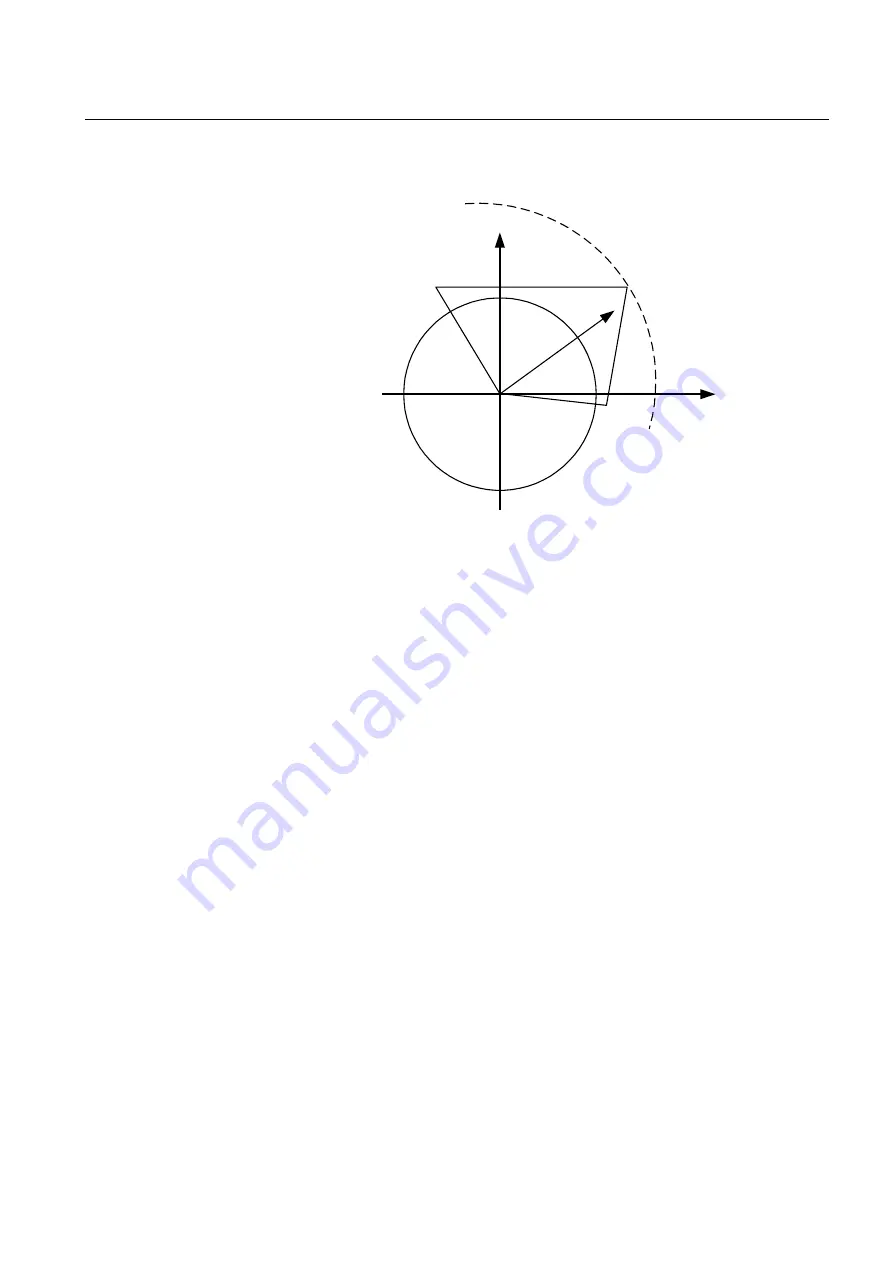
)LJXUH 0HDVXUHPHQWSULQFLSOHVIRUWKHLPSHGDQFHSURWHFWLRQ
A resistance and reactance calculation with a complex power comparison is performed
between the circles according to the formula:
(Equation 20)
A counter tracks how many times the set operate conditions are fulfilled. This is done
to eliminate the risk for unwanted/faulty operation due to transient measurement uncer-
tainty. When the total exceeds a level that corresponds to 2/3 periods, a memory ele-
ment is activated to mark that the measured impedance is low.
The slope for the directional lines is calculated in the same way, but by using memory
voltage. As the phase position of the voltage is available for a further period during the
fault, a selective determination of direction can be made, even if the fault voltage is very
low. If the fault voltage remains low and the fault current exceeds the lowest operate
current, tripping is completed if the impedance is low. If the fault is in the reverse di-
rection, the reverse directional measuring element will remain functional.
R
jX
en02000640.vsd
S
U I
*
R
set
j X
set
⋅
+
(
)
I
2
⋅
<
⋅
=
Summary of Contents for REO 517
Page 10: ... RQWHQWV ...
Page 16: ...6 Introduction to the application manual KDSWHU QWURGXFWLRQ ...
Page 64: ...54 Blocking of signals during test KDSWHU RPPRQ IXQFWLRQV ...
Page 88: ...78 Scheme communication logic ZCOM KDSWHU LQH LPSHGDQFH ...
Page 146: ...136 Unbalance protection for capacitor banks TOCC KDSWHU XUUHQW ...
Page 166: ...156 Dead line detection DLD KDSWHU 3RZHU V VWHP VXSHUYLVLRQ ...
Page 378: ...368 Monitoring of DC analog measurements KDSWHU 0RQLWRULQJ ...
Page 384: ...374 Pulse counter logic PC KDSWHU 0HWHULQJ ...
Page 412: ...402 Serial communication modules SCM KDSWHU DWD FRPPXQLFDWLRQ ...
Page 440: ...430 LED indication module KDSWHU DUGZDUH PRGXOHV ...


