65
3 zone impedance protection (Z(n)RW)
&KDSWHU
/LQHLPSHGDQFH
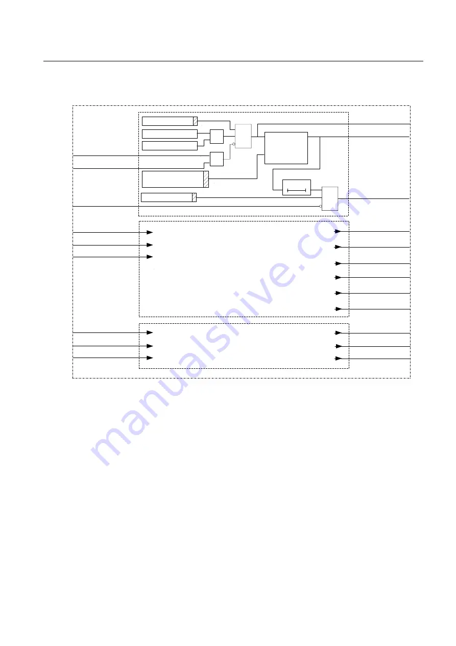
)LJXUH 6LPSOLILHGORJLFGLDJUDPIRULPSHGDQFHSURWHFWLRQ
The impedance zone 1 is activated by setting the parameter Operation=Forward, Re-
verse or NonDir and is blocked with the setting Operation=Off.
Zone 1 can be delayed by setting Function t1=On on the setting menu. For instanta-
neous function, set Function t1=On and t1=0,000 for the actual zone. All three zones
have the same logical structure.
ZONE 2
ZONE 3
Timer t1=On
ZONE 1
Z1RW-BLKTR
en02000642.vsd
Z2RW-VTSZ
Z2RW-BLOCK
Z2RW-BLKTR
Z3RW-VTSZ
Z3RW-BLOCK
Z3RW-BLKTR
Z1RW-START
Z1RW-TRIP
Z2RW-START
Z3RW-START
Z3RW-TRIP
Z2RW-TRIP
Z2RW-NDSTL1N
Z2RW-NDSTL2N
Z2RW-NDSTL1L2
Z3RW-NDST
Z2RW-NDST
Z1RW-VTSZ
Z1RW-BLOCK
≥
1
U
I
Z<
Operation =On
Z1RW-NDST
Direction
check
t
t1
Operation =
NonDir/Rev/For
Summary of Contents for REO 517
Page 10: ... RQWHQWV ...
Page 16: ...6 Introduction to the application manual KDSWHU QWURGXFWLRQ ...
Page 64: ...54 Blocking of signals during test KDSWHU RPPRQ IXQFWLRQV ...
Page 88: ...78 Scheme communication logic ZCOM KDSWHU LQH LPSHGDQFH ...
Page 146: ...136 Unbalance protection for capacitor banks TOCC KDSWHU XUUHQW ...
Page 166: ...156 Dead line detection DLD KDSWHU 3RZHU V VWHP VXSHUYLVLRQ ...
Page 378: ...368 Monitoring of DC analog measurements KDSWHU 0RQLWRULQJ ...
Page 384: ...374 Pulse counter logic PC KDSWHU 0HWHULQJ ...
Page 412: ...402 Serial communication modules SCM KDSWHU DWD FRPPXQLFDWLRQ ...
Page 440: ...430 LED indication module KDSWHU DUGZDUH PRGXOHV ...


