8.
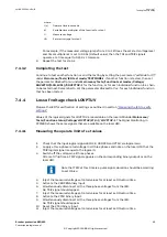
Activate the BLOCK binary input.
The signals ALARM, START and TRIP should disappear.
9.
Reset the BLOCK binary input.
10. Check the reset limit (TdReset).
Monitor the signal START until it disappears on the corresponding binary output or on
the local HMI, take the TEMP readings and compare with the setting of
ReclTemp.
11.
Compare the measured trip time with the setting according to the formula.
12.
Reset the thermal memory.
13. Continue to test another function or end the test by changing the test mode setting to
Off.
7.3.8.2
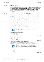
Completing the test
M14950-48 v5
Continue to test another function or end the testing by setting the parameter
TestMode to Off
under Main menu/Tests/IED test mode/TESTMODE:1. If another function is tested, then set
the parameter
Blocked to No under Main menu/Tests/Function test modes/Current/
LCPTTR(26,T>)/LCPTTR:1, Main menu/Tests/Function test modes/Current/LFPTTR(26,T>)/
LFPTTR:1 for the function, or for each individual function in a chain, to be tested next.
Remember to set the parameter
Blocked to Yes, for each individual function that has been
tested.
7.3.9
Breaker failure protection, phase segregated activation and
output CCRBRF
M12104-2 v9.1.1
Prepare the IED for verification of settings as outlined in section
Values of the logical signals for CCRBRF are available on the local HMI under Main menu/
Tests/Function status/Current/CCRBRF(50BF)/CCRBRF:1. The Signal Monitoring in PCM600
shows the same signals that are available on the local HMI.
The Breaker failure protection, 3-phase activation and output function CCRBRF should
normally be tested in conjunction with some other function that provides a start signal. An
external START signal can also be used.
To verify the settings in the most common back-up trip mode
1 out of 3, it is sufficient to test
phase-to-earth faults.
At mode
2 out of 4 the phase current setting, IP> can be checked by single-phase injection
where the return current is connected to the summated current input. The value of residual
(earth fault) current IN set lower than
IP> is easiest checked in back-up trip mode 1 out of 4.
7.3.9.1
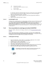
Checking the phase current operate value,
IP>
M12104-23 v7
Check the current level
IP> where setting FunctionMode=Current and setting BuTripMode=1
out of 3 or 2 out of 4 as set under Main menu/Settings/IED Settings/Current/
CCRBRF(50BF)/CCRBRF:1.
1.
Apply the fault condition, including START of CCRBRF, with a current below set
IP>.
2.
Repeat the fault condition and increase the current in steps until a trip occurs.
3.
Compare the result with the set
IP>.
4.
Disconnect AC and START input signals.
Section 7
1MRK 505 293-UEN B
Testing functionality
54
Breaker protection REQ650
Commissioning manual
© Copyright 2013 ABB. All rights reserved
Summary of Contents for REQ650 1.3 IEC
Page 1: ...Relion 650 SERIES Breaker protection REQ650 Version 1 3 IEC Commissioning manual ...
Page 2: ......
Page 12: ...6 ...
Page 20: ...14 ...
Page 28: ...22 ...
Page 40: ...34 ...
Page 42: ...36 ...
Page 116: ...110 ...
Page 123: ...117 ...


