background image

25.  Certificates

KEMA has issued an IEC 61850 Certificate Level
A1 for Relion

®

 615 series. Certificate number:

30920420-Consulting 09-1712.

Det Norske Veritas (DNV) has issued a Type
Approval Certificate for RET615. Certificate
number: E-11189.

26.  References

The 

www.abb.com/substationautomation

 portal

offers you information about the distribution
automation product and service range.

You will find the latest relevant information on the
RET615 protection IED on the 

product page

.

The download area on the right hand side of the
web page contains the latest product
documentation, such as technical manual,
installation manual, operation manual, etc.

The Features and Application tabs contain
product related information in a compact format.

GUID-88EE01E3-7520-46F6-96A1-E0965DC9A468 V1 EN

Figure 21.

Product page

Transformer Protection and Control

1MRS756891 F

RET615


Product version: 4.0


ABB

61

Summary of Contents for RET615

Page 1: ...Relion 615 series Transformer Protection and Control RET615 Product Guide...

Page 2: ...2 Accessories and ordering data 56 23 Tools 57 24 Terminal diagrams 59 25 Certificates 61 26 References 61 27 Functions codes and symbols 62 28 Document revision history 64 Disclaimer The information...

Page 3: ...nfigurations Description Std conf Three phase transformer differential protection for two winding transformers numerical restricted earth fault protection for the high voltage HV side optional RTD mA...

Page 4: ...directional overcurrent protection low stage instance 1 Three phase non directional overcurrent protection high stage instance 1 Three phase non directional overcurrent protection instantaneous stage...

Page 5: ...on instance 2 Arc protection instance 111 o o o o o o o o Arc protection instance 211 o o o o o o o o Arc protection instance 311 o o o o o o o o Control Disconnector control instance 1 3 3 3 3 3 3 3...

Page 6: ...r 1 The instances of a protection function represent the number of identical function blocks available in a standard configuration By setting the application specific parameters of an instance a prote...

Page 7: ...racter and absolute selectivity REF does not need to be time graded with other protection schemes and therefore high speed fault clearance can be achieved The IED also incorporates a thermal overload...

Page 8: ...GUID 987FF881 286F 44E3 A24B 4A3C2A137C26 V3 EN Figure 1 Protection function overview of standard configuration A Transformer Protection and Control 1MRS756891 F RET615 Product version 4 0 8 ABB...

Page 9: ...GUID E197B2BA 0E91 413E 9462 7E2FEE2D320F V3 EN Figure 2 Protection function overview of standard configuration B Transformer Protection and Control 1MRS756891 F RET615 Product version 4 0 ABB 9...

Page 10: ...GUID A68F1E1E 49FA 4B6C 9F18 1099F998F9EE V3 EN Figure 3 Protection function overview of standard configuration C Transformer Protection and Control 1MRS756891 F RET615 Product version 4 0 10 ABB...

Page 11: ...GUID B23D25EF 1130 4D27 8E46 1F3ADD5851EB V3 EN Figure 4 Protection function overview of standard configuration D Transformer Protection and Control 1MRS756891 F RET615 Product version 4 0 ABB 11...

Page 12: ...GUID E97CBFCA ED41 41FC 829F F985B5E1EEAE V2 EN Figure 5 Protection function overview of standard configuration E Transformer Protection and Control 1MRS756891 F RET615 Product version 4 0 12 ABB...

Page 13: ...GUID 11D1A6F8 56EC 493B 8FCB E8CF85A8EC43 V2 EN Figure 6 Protection function overview of standard configuration F Transformer Protection and Control 1MRS756891 F RET615 Product version 4 0 ABB 13...

Page 14: ...GUID 4FA574C4 CC3B 4ED7 BB3B 3FAC6B013360 V2 EN Figure 7 Protection function overview of standard configuration G Transformer Protection and Control 1MRS756891 F RET615 Product version 4 0 14 ABB...

Page 15: ...GUID 65E42643 971A 42E7 B083 DC461276A779 V2 EN Figure 8 Protection function overview of standard configuration H Transformer Protection and Control 1MRS756891 F RET615 Product version 4 0 ABB 15...

Page 16: ...tection and measurement functions which provide two stage power transformer overvoltage and undervoltage protection and or supervision The optional RTD mA module offered for the standard configuration...

Page 17: ...ion on the HV side In addition a REF615 with the standard configuration F is used on the LV side to provide besides O C and E F back up protection busbar overvoltage and undervoltage protection Furthe...

Page 18: ...d substation level functionality COM600 features a web browser based HMI providing a customizable graphical display for visualizing single line mimic diagrams for switchgear bay solutions The SLD feat...

Page 19: ...ries IEDs Grid Automation controller COM600 and System 800xA 6 Control RET615 integrates functionality for the control of a circuit breaker via the front panel HMI or by means of remote controls In ad...

Page 20: ...and the low voltage LV side phase currents and the neutral current of the protected transformer In addition the IED calculates the symmetrical components of the currents and voltages maximum current d...

Page 21: ...f the trip circuit It provides open circuit monitoring both when the circuit breaker is in its closed and in its open position It also detects loss of circuit breaker control voltage 13 Self supervisi...

Page 22: ...any Ethernet based application in the standard COMTRADE file format The IED supports simultaneous event reporting to five different clients on the station bus The IED can send binary signals to other...

Page 23: ...ts retrieval of time stamped events changing the active setting group and uploading of the latest fault records If a Modbus TCP connection is used five clients can be connected to the IED simultaneous...

Page 24: ...19C V3 EN Figure 12 Self healing Ethernet ring solution Table 5 Supported station communication interfaces and protocols Interfaces Protocols Ethernet Serial 100BASE TX RJ 45 100BASE FX LC RS 232 RS 4...

Page 25: ...tion time in the auxiliary DC voltage without resetting the IED 50 ms at Unrated Uauxvariation 38 110 of Un 38 264 V AC 50 120 of Un 12 72 V DC 80 120 of Un 38 4 300 V DC Start up threshold 19 2 V DC...

Page 26: ...nputs Rated voltage 60 210 V AC Voltage withstand Continuous 240 V AC For 10 s 360 V AC Burden at rated voltage 0 05 VA 1 Residual current and or phase current Table 9 Binary inputs Description Value...

Page 27: ...RTD resistance sensing current Maximum 0 33 mA rms Operation accuracy Resistance Temperature 2 0 or 1 1 C 10 copper 2 C mA inputs Supported current range 0 20 mA Current input impedance 44 0 1 Operat...

Page 28: ...in series 5 A 3 A 1 A Minimum contact load 100 mA at 24 V AC DC Trip circuit supervision TCS Control voltage range 20 250 V AC DC Current drain through the supervision circuit 1 5 mA Minimum voltage...

Page 29: ...Modulation Unmodulated Logic level TTL Level Current consumption 2 4 mA Power consumption 10 20 mW 1 According to 200 04 IRIG standard Table 18 Lens sensor and optical fibre for arc protection Descri...

Page 30: ...interface the maximum operating temperature is 70 C Table 21 Environmental tests Description Type test value Reference Dry heat test 96 h at 55 C 16 h at 85 C1 IEC 60068 2 2 Dry cold test 96 h at 25 C...

Page 31: ...ass III 10 V m rms f 80 2700 MHz IEC 61000 4 3 IEC 60255 22 3 class III 10 V m f 900 MHz ENV 50204 IEC 60255 22 3 class III 20 V m rms f 80 1000 MHz IEEE C37 90 2 2004 Fast transient disturbance test...

Page 32: ...m distance 230 1000 MHz 47 dB V m quasi peak measured at 10 m distance Table 23 Insulation tests Description Type test value Reference Dielectric tests 2 kV 50 Hz 1 min 500 V 50 Hz 1 min communicatio...

Page 33: ...2005 EN 60255 1 2009 Table 26 EMC compliance Description Reference EMC directive 2004 108 EC Standard EN 50263 2000 EN 60255 26 2007 Table 27 RoHS compliance Description Complies with RoHS directive 2...

Page 34: ...Typical 0 96 Retardation time 30 ms Operate time accuracy in definite time mode 1 0 of the set value or 20 ms Operate time accuracy in inverse time mode 5 0 of the theoretical value or 20 ms 3 Suppres...

Page 35: ...0 05 15 00 0 01 Operate delay time PHLPTOC 40 200000 ms 10 PHHPTOC 40 200000 ms 10 PHIPTOC 20 200000 ms 10 Operating curve type1 PHLPTOC Definite or inverse time Curve type 1 2 3 4 5 6 7 8 9 10 11 12...

Page 36: ...t time 40 ms Reset ratio Typical 0 96 Retardation time 30 ms Operate time accuracy in definite time mode 1 0 of the set value or 20 ms Operate time accuracy in inverse time mode 5 0 of the theoretical...

Page 37: ...e Operation accuracy Depending on the frequency of the voltage measured fn 2 Hz 1 5 of the set value or 0 002 x Un Start time1 2 Minimum Typical Maximum UFault 1 1 x set Start value 55 ms 56 ms 58 ms...

Page 38: ...50 dB at f n x fn where n 2 3 4 5 1 Negative sequence current before fault 0 0 fn 50 Hz results based on statistical distribution of 1000 measurements 2 Includes the delay of the signal output contac...

Page 39: ...e 1 0 x Un Voltage before fault 0 9 x Un fn 50 Hz overvoltage in one phase to phase with nominal frequency injected from random phase angle results based on statistical distribution of 1000 measuremen...

Page 40: ...of 1000 measurements 2 Includes the delay of the signal output contact 3 Minimum Start value 0 50 Start value multiples in range of 0 90 to 0 20 Table 39 Three phase undervoltage protection PHPTUV mai...

Page 41: ...ng transformers TR2PTDF Characteristic Value Operation accuracy Depending on the frequency of the current measured fn 2 Hz 3 0 of the set value or 0 002 x In Operate time1 2 Minimum Typical Maximum Lo...

Page 42: ...500 3000 10 Low operate value TR2PTDF 5 50 1 Slope section 2 TR2PTDF 10 50 1 End section 2 TR2PTDF 100 500 1 Start value 2 H TR2PTDF 7 20 1 Start value 5 H TR2PTDF 10 50 1 Operation TR2PTDF Off On Wi...

Page 43: ...e 1 0 of the set value or 20 ms Suppression of harmonics DFT 50 dB at f n x fn where n 2 3 4 5 1 Current before fault 0 0 fn 50 Hz results based on statistical distribution of 1000 measurements 2 Incl...

Page 44: ...t before fault 0 0 fn 50 Hz results based on statistical distribution of 1000 measurements 2 Includes the delay of the signal output contact Table 47 High impedance based restricted earth fault protec...

Page 45: ...n mode Light current 1 2 9 ms 12 ms 15 ms Operation mode Light only 2 9 ms 10 ms 12 ms Reset time 40 ms Reset ratio Typical 0 96 1 Phase start value 1 0 x In current before fault 2 0 x set Phase start...

Page 46: ...inv 2 ANSI Very inv 3 ANSI Norm inv 4 ANSI Mod inv 5 ANSI Def Time 6 L T E inv 7 L T V inv 8 L T inv 9 IEC Norm inv 10 IEC Very inv 11 IEC inv 12 IEC Ext inv 13 IEC S T inv 14 IEC L T inv 15 IEC Def...

Page 47: ...ppression of harmonics DFT 50 dB at f n x fn where n 2 3 4 5 RMS No suppression Table 57 Voltage sequence components VSMSQI Characteristic Value Operation accuracy Depending on the frequency of the vo...

Page 48: ...ower and energy PEMMXU Characteristic Value Operation accuracy At all three currents in range 0 10 1 20 x In At all three voltages in range 0 50 1 15 x Un At the frequency fn 1 Hz Active power and ene...

Page 49: ...rted resistance range 0 2 k Maximum lead resistance three wire measurement 25 per lead Isolation 2 kV inputs to protective earth Response time 4 s RTD resistance sensing current Maximum 0 33 mA rms Op...

Page 50: ...ssed using the web browser based user interface The default SLD can be modified according to user requirements by using the graphical display editor in PCM600 The local HMI includes a push button L R...

Page 51: ...two IEDs Alternatively the IED can be mounted in 19 instrument cabinets by means of 4U Combiflex equipment frames For the routine testing purposes the IED cases can be equipped with test switches typ...

Page 52: ...r part of the plug in unit An order number label is placed on the side of the plug in unit as well as inside the case The order number consists of a string of codes generated from the IED s hardware a...

Page 53: ...ide phase voltage based protection and measurement functions and CB control G Three phase transformer differential protection for two winding transform ers high impedance based restricted earth fault...

Page 54: ...net 100Base TX and FX 1 x RJ 45 2 x LC NE No communication module NN The communication module hardware determines the available communication proto cols Choose the hardware from one of the rows below...

Page 55: ...ion module cannot be combined with communication modules BN or BB B None N 15 Option 2 None N 16 Power supply 48 250 V DC 100 240 V AC 1 24 60 V DC 2 17 18 Version Version 4 0 XE H B T A B G B A B C C...

Page 56: ...test switch the test switch is not included in the delivery 2RCA021952A0003 19 rack mounting kit for one IED and one RTXP24 test switch the test switch is not included in the delivery 2RCA022561A0003...

Page 57: ...rowser based user interface is disabled by default The interface can be enabled with the PCM600 tool or from the front panel user interface The functionality of the interface can be limited to read on...

Page 58: ...management DNP3 communication configuration communication management IEC 60870 5 103 communication configuration communication management Saving of IED parameter settings in the tool Disturbance reco...

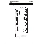
Page 59: ...erminal diagrams GUID 3CB989EB 6ECA 471F 8692 DB15C1DE5EFB V2 EN Figure 19 Terminal diagram of standard configurations A D Transformer Protection and Control 1MRS756891 F RET615 Product version 4 0 AB...

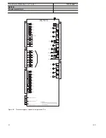
Page 60: ...GUID 3655E0AF 034F 4D63 B098 5B5321A13662 V1 EN Figure 20 Terminal diagram of standard configurations E H Transformer Protection and Control 1MRS756891 F RET615 Product version 4 0 60 ABB...

Page 61: ...automation product and service range You will find the latest relevant information on the RET615 protection IED on the product page The download area on the right hand side of the web page contains th...

Page 62: ...PTOC2 I2 2 46 2 Residual overvoltage protection ROVPTOV1 Uo 1 59G 1 ROVPTOV2 Uo 2 59G 2 Three phase undervoltage protection PHPTUV1 3U 1 27 1 PHPTUV2 3U 2 27 2 Three phase overvoltage protection PHPTO...

Page 63: ...ndication ESSXSWI1 I O ES 1 I O ES 1 ESSXSWI2 I O ES 2 I O ES 2 Tap changer position indication TPOSSLTC1 TPOSM 84M Condition monitoring Circuit breaker condition monitoring SSCBR1 CBCM CBCM Trip circ...

Page 64: ...X130 RTD 28 Document revision history Document revision date Product version History A 2009 07 03 2 0 First release B 2009 10 01 2 0 Content updated C 2010 06 11 3 0 Content updated to correspond to...

Page 65: ...65...

Page 66: ......

Page 67: ......

Page 68: ...Contact us ABB Oy Distribution Automation P O Box 699 FI 65101 VAASA Finland Phone 358 10 22 11 Fax 358 10 22 41094 www abb com substationautomation 1MRS756891 F Copyright 2012 ABB All rights reserved...

Reviews: