background image

ABB Drives

User’s Manual
Ethernet Adapter Module 
RETA-01

Summary of Contents for RETA-01

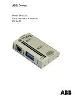
Page 1: ...ABB Drives User s Manual Ethernet Adapter Module RETA 01 ...

Page 2: ......

Page 3: ...Ethernet Adapter Module RETA 01 User s Manual 3AFE64539736 REV C EN EFFECTIVE 8 8 2006 2006 ABB Oy All Rights Reserved ...

Page 4: ......

Page 5: ...rive and adjoining equipment must be properly earthed Do not attempt any work on a powered drive After switching off the mains always allow the intermediate circuit capacitors 5 minutes to discharge before working on the frequency converter the motor or the motor cable It is good practice to check with a voltage indicating instrument that the drive is in fact discharged before beginning work The m...

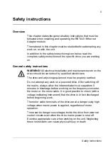
Page 6: ...Safety instructions 6 ...

Page 7: ...nual contains 11 Terms used in this manual 12 Overview 15 Overview 15 Modbus TCP 15 EtherNet IP 15 The RETA 01 Ethernet Adapter module 16 Compatibility 17 Delivery check 17 Warranty and liability information 18 Quick start up guide 19 Overview 19 Preliminary preparation 19 Mechanical installation 19 Electrical installation 19 Drive configuration 19 Network configuration 20 Communication 21 ...

Page 8: ...nfiguration 33 Overview 33 RETA 01 configuration 33 Network configuration 41 Overview 41 Data transfer rates supported 44 Other network components 44 Communication profiles 45 The ODVA AC DC drive profile 45 ODVA output attributes 46 ODVA input attributes 47 ABB Drives communication profile 49 The control word and the status word 49 References 50 Actual values 50 Communication 51 Overview 51 Proto...

Page 9: ...Class 0x01 63 Message Router Class 0x02 67 Assembly Objects Class 0x04 67 Connection Manager Class 0x06 68 Motor Data Object Class 0x28 68 Control Supervisor Object Class 0x29 69 AC DC Drive Object Class 0x2A 71 Vendor Specific Object Class 0x90 73 Drive IO Map Object Class 0x91 75 Configuration Object Class 0x92 76 TCP IP Interface Object Class 0xF5 77 Ethernet Link Object Class 0xF6 79 Fault tra...

Page 10: ...Table of Contents 10 ...

Page 11: ...mportant information not included in this manual The drive manuals are referred to at various points of this document What this manual contains This manual contains information on the wiring configuration and use of the RETA 01 Ethernet Adapter module Safety instructions are featured in the first few pages of this manual Overview contains a short description of the Ethernet protocols and the RETA ...

Page 12: ...al Communication Module Communication Module is a name for a device e g a fieldbus adapter through which the drive is connected to an external communication network e g a fieldbus The communication with the module is activated with a drive parameter MAC ID Every node on Ethernet network has to have a unique identifier This node number is called MAC ID Media Access Control ID Data Sets and Data Wor...

Page 13: ...formation Each piece of data communicated by a device is represented by an attribute in one of the device s internal objects Communicating multiple pieces of data attributes across a single I O connection requires that the attributes are grouped or assembled together into a single block Parameter A parameter is an operating instruction for the drive Parameters can be read and programmed with the d...

Page 14: ...Introduction 14 ...

Page 15: ...odbus TCP server in the RETA 01 module is done according to the Modbus TCP Specification 1 0 The supported Modbus commands are listed in chapter Communication The Modbus TCP protocol allows the RETA 01 module to be used as an Ethernet bridge to control the drive The RETA 01 module supports eight simultaneous IP connections Further information can be obtained from www modbus org EtherNet IP EtherNe...

Page 16: ...ce to the drive give a process actual value or a process reference to the PID controller of the drive read status information and actual values from the drive change drive parameter values reset a drive fault The Modbus TCP and EtherNet IP commands and services supported by the RETA 01 Ethernet Adapter module are discussed in chapter Communication Please refer to the user documentation of the driv...

Page 17: ...1 Ethernet Adapter module contains Ethernet Adapter module type RETA 01 two screws M3x10 this manual Ethernet connector X1 see chapter Electrical installation Diagnostic LEDs See chapter Fault tracing DIP switch for selecting intranet IP address Fixing screw GND frame Top view Side view RETA 01 PROFIBUS ADAPTER CHASSIS X1 NETWORK S1 IP ADDRESS NOT USED LINK ACTIVITY MODULE STATUS NETWORK STATUS GN...

Page 18: ...n commissioning repair alternation or ambient conditions of the drive do not fulfil the requirements specified in the documentation delivered with the unit and other relevant documentation units subjected to misuse negligence or accident units comprised of materials provided or designs stipulated by the purchaser In no event shall the manufacturer its suppliers or subcontractors be liable for spec...

Page 19: ...ion of the module write down the MAC ID of the module Printed on a sticker on the back of the module Make sure you have the two screws for fastening the module Mechanical installation Insert the RETA 01 into its specified slot in the drive SLOT2 for ACS550 SLOT1 for ACS800 Fasten the two screws Electrical installation Connect the Ethernet cable RJ 45 connector to the RETA 01 module Standard CAT 5 ...

Page 20: ...ation parameters Network configuration To enable communication through the Ethernet network the module needs a valid IP address There are numerous ways of setting the module IP address see chapter Network configuration One way of setting the IP address is to use the ARP Address Resolution Protocol command from a PC The new IP address will be stored in the RETA 01 configuration parameters An exampl...

Page 21: ...CP or EtherNet IP protocol The protocol and communication profile used in the application can be selected with a RETA 01 configuration parameter PROTOCOL Note With ACS550 the profile selection is automatic With ACS800 the profile must be selected with parameter 98 07 as follows Modbus TCP 98 07 ABB DRIVES Ethernet IP AC DC communication profile 98 07 GENERIC Ethernet IP ABB Drives communication pr...

Page 22: ...Add RETA 01 adapter to device configuration Figure 2 RSlogix 5000 Adding new module to I O Configuration Set comm Format to Data INT IP address input and output assemblies and their sizes Disable the Configuration assembly instance 1 by setting its size to 0 ...

Page 23: ...Quick start up guide 23 Use class instance editor to edit the attributes of Ethernet IP objects if necessary Figure 3 RSNetWorks for Ethernet IP Class Instance Editor ...

Page 24: ...plication Set comm Format to Data INT Set IP address to 10 0 0 6 Set input assembly instance to 71 and size to 2 Set output assembly instance to 21 and size to 2 Set configuration instance to 1 and size to 0 Figure 4 RSlogix 5000 Setting up the Generic Ethernet Module to use Extended Speed Control assembly ...

Page 25: ...3 REF DIRECTION REQUEST 11 03 EXT1 REF1 SELECT COMM REF 16 04 FAULT RESET SEL COMM CW 98 02 COMM MODULE LINK FIELDBUS 98 07 COMM PROFILE GENERIC 51 01 MODULE TYPE ETHERNET 51 02 COMM RATE 0 Auto negotiation 51 03 DHCP 1 Enabled 51 04 51 07 IP ADDRESS 10 0 0 6 51 08 51 11 SUBNET MASK 255 255 255 0 51 12 51 15 GW ADDRESS 0 0 0 0 51 16 PROTOCOL 1 AC DC profile ...

Page 26: ...on ACS550 Set comm Format to Data INT Set IP address to 10 0 0 6 Set input instance to 103 and size to 3 Set output instance to 102 and size to 2 Set configuration instance to 1 and size to 0 Figure 6 RSlogix 5000 Setting up the Generic Ethernet Module to use User Specific Control assembly ...

Page 27: ...T SEL COMM 98 02 COMM PROT SEL EXT FBA 51 01 MODULE TYPE ETHERNET 51 02 COMM RATE 0 Auto negotiation 51 03 DHCP 1 Enabled 51 04 51 07 IP ADDRESS 10 0 0 6 51 08 51 11 SUBNET MASK 255 255 255 0 51 12 51 15 GW ADDRESS 0 0 0 0 51 16 PROTOCOL 2 ABB Drives profile 51 19 OUTPUT 1 1 Command word 51 20 OUTPUT 2 2 Reference 1 51 23 INPUT 1 4 Status word 51 24 INPUT 2 5 Actual value 1 51 25 INPUT 3 104 Par 1...

Page 28: ...Quick start up guide 28 ...

Page 29: ...le and interconnect the GND signals of the module and the control board of the drive On installation of the module the signal and power connection to the drive is automatically made through a 34 pin connector Mounting procedure Insert the module carefully into its position inside the drive until the retaining clips lock the module into position Fasten the two screws included to the stand offs Set ...

Page 30: ...Mechanical installation 30 ...

Page 31: ...ions Arrange the network cable as far away from the motor cables as possible Avoid parallel runs Use bushings at cable entries Ethernet connection The network cable is connected to the RJ45 connector X1 on the RETA 01 module Standard CAT 5 UTP and CAT 5 STP cables can be used In case CAT 5 STP is used the cable shield is internally connected to drive frame through the module ...

Page 32: ...Electrical installation 32 ...

Page 33: ...t Stop Direction Reference Fault Reset etc In order to give the fieldbus master station the most complete control over the drive the communication module must be selected as source for this information The detailed procedure of activating the drive for communication with the module is dependent on the drive type Normally a parameter must be adjusted to activate the communication Please refer to th...

Page 34: ... enabled 4 IP address 1 0 255 0 5 IP address 2 0 255 0 6 IP address 3 0 255 0 7 IP address 4 0 255 0 8 Subnet mask 1 0 255 0 9 Subnet mask 2 0 255 0 10 Subnet mask 3 0 255 0 11 Subnet mask 4 0 255 0 12 GW address 1 0 255 0 13 GW address 2 0 255 0 14 GW address 3 0 255 0 15 GW address 4 0 255 0 0 16 Protocol 0 Modbus TCP 1 Ethernet IP AC DC communication profile 2 Ethernet IP ABB Drives communicati...

Page 35: ...DHCP is an Internet protocol for automating the configuration of computers that use TCP IP DHCP can be used to automatically assign IP addresses to deliver TCP IP stack configuration parameters such as the subnet mask and default router and to provide other configuration information 21 Output 3 0 65535 0 22 Output 4 0 65535 0 23 Input 1 0 65535 0 24 Input 2 0 65535 0 25 Input 3 0 65535 0 26 Input ...

Page 36: ...fourth octet is defined by the DIP switch See chapter Network configuration 8 Subnet mask 1 9 Subnet mask 2 10 Subnet mask 3 11 Subnet mask 4 Subnet masks are used for splitting networks into subgroups or subnets A subnet mask is a binary pattern that is matched up with the IP address to turn part of the address field into a field for subnets These parameters define the four octets of the subnet m...

Page 37: ...ion fault function of the drive is activated Modbus timeout is the sum of communication fault time and the time defined here 18 Stop function Defines the motor stopping method Note This parameter is only effective if the EtherNet IP network protocol is selected at parameter 16 Protocol 19 Output 1 20 Output 2 21 Output 3 22 Output 4 When Modbus TCP protocol is in use these parameters define the ou...

Page 38: ...en the drive and RETA 01 For the user this can be seen as faster response for the Modbus queries When Ethernet IP protocol is in use these parameters define the data words or drive parameters that can be read using Assembly object instance 103 see chapter Communication 0 Not used 1 99 Data set area of the drive 1 Data set 1 word 1 2 Data set 1 word 2 3 Data set 1 word 3 4 Data set 2 word 1 5 Data ...

Page 39: ...ve 1 Data set 1 word 1 2 Data set 1 word 2 3 Data set 1 word 3 4 Data set 2 word 1 5 Data set 2 word 2 99 Data set 33 word 3 101 9999 Parameter area of the drive Format x xyy where x x actual signal group or parameter group yy actual signal or parameter index E g 103 actual signal 01 03 2202 parameter 22 02 10000 65535 Not supported by the drive ...

Page 40: ...Drive configuration 40 ...

Page 41: ...which different settings are read The table below gives detailed information on each different configuration methods Start End DIP switches 0 Use DHCP DHCP server timeout RETA 01 config parameters 0 Wait for config through Gleaning Configuration received Use stored settings Use configuration from DHCP server Use 192 168 0 xxx xxx DIP setting No No No No No Yes Yes Yes Yes Yes ...

Page 42: ...binary Actuator 8 represents the least significant bit Only read at start up Only for intranet use IP address 192 168 0 xxx Subnet mask 255 255 255 0 Gateway 0 0 0 0 where xxx stands for a value between 1 and 254 and is selected by DIP switch S1 Example DIP settings Intranet IP address S1 actuator positions Selected by software OFF oooooooo ON 12345678 192 168 0 1 OFF ooooooo ON o 12345678 192 168...

Page 43: ...shed RETA 01 configuration parameter 27 REFRESH for anyconfiguration changes to take effect Gleaning ARP Change the IP address from a PC using the following commands arp s IP address MAC address ping IP address arp d IP address The arp s command will store the IP and MAC addresses in the PC ARP table When the ping command is executed the PC will send the message to the module using the MAC address...

Page 44: ...s Ethernet switches require a feature called IGMP Snooping Internet Group Management Protocol to avoid network load caused by the multicast messages IGMP Snooping simply confirms that multicast messages are sent to correct devices EtherNet IP Send IP parameters to the TCP IP Interface object Class 0xF5 RETA 01 must be restarted or parameters refreshed RETA 01 configuration parameter 27 REFRESH for...

Page 45: ... ABB Drives profile The ODVA AC DC drive profile This section briefly describes the ODVA AC DC Drive profiles Additional information can be obtained from www odva org An Ethernet IP node is modelled as a collection of abstract objects Each object represents the interface to and behaviour of a component within the product The ODVA AC DC Drive Profiles define a collection of objects suitable for the...

Page 46: ... 55 ODVA output attributes This section briefly describes the instances found in the ODVA AC DC Drive Profiles output assemblies Not all attributes listed here will be supported by all output assembly instances Run Forward Run Reverse Control Supervisor Object These attributes are used to assert run and stop commands to Control Supervisor Object state machine according to the following table Table...

Page 47: ... DC Drive Object ODVA input attributes This section briefly describes the instances found in the ODVA AC DC Drive Profiles input assemblies Not all attributes listed here will be supported by all input assembly instances Faulted Control Supervisor Object This attribute indicates that the drive has experienced a fault The fault code may be read from the FaultCode attribute of the Control Supervisor...

Page 48: ...f From Net AC DC Drive Object This attribute indicates if the Speed and Torque references are being supplied locally Ref From Net 0 or by the network Ref From Net 1 At Reference AC DC Drive Object This attribute indicates the drive is operating at the specified speed or torque reference State Control Supervisor Object This attribute indicates the current state of the Control Supervisor Object Tabl...

Page 49: ...ect ABB Drives communication profile The control word and the status word The Control Word is the principal means for controlling the drive from a fieldbus system It is sent by the fieldbus master station to the drive through the adapter module The drive switches between its states according to the bit coded instructions on the Control Word and returns status information to the master in the Statu...

Page 50: ...ed by calculating the two s complement from the corresponding positive reference Actual values Actual values are 16 bit words containing information on the operation of the drive The functions to be monitored are selected by a drive parameter Note For detailed description of the drive s control word status word references and actual signals see the firmware manual of the drive ...

Page 51: ...ribes the Modbus TCP and EtherNet IP messaging used in the communication with the drive Protocols The RETA 01 module supports the Modbus TCP protocol according to Modbus TCP Specification 1 0 and the EtherNet IP protocol User must select which protocol to use ...

Page 52: ...s directly to the drive parameter grouping which is being used by the local drive control panel All parameters are available for reading The parameter writes are verified for correct value and for valid register addresses Some parameters never allow writing e g actual signals some allow writing only when the drive is stopped e g set up variables and some can be modified at any time Register mappin...

Page 53: ...d in a cyclic interval Updating of parameter registers happens at a slower interval Parameter 4GGPP GG PP Data sets Each data set consists of 3 data words For example Data word 2 3 refers to the 3rd word in data set 2 40001 40096 00 Data sets 01 Data word 1 1 02 Data word 1 2 03 Data word 1 3 04 Data word 2 1 05 Data word 2 2 06 Data word 2 3 07 Data word 3 1 94 Data word 32 1 95 Data word 32 2 96...

Page 54: ...imum and maximum limits Parameter is read only Function code Name Description Modbus class 03 Read hold ing registers Reads the binary contents of the holding registers 4X references in the slave 0 06 Preset sin gle register Presets a value into a single hold ing register 4X reference 1 16 10h Preset multi ple registers Presets values into a sequence of holding registers 4X references 0 23 17h Rea...

Page 55: ...ndor specific objects A group of objects can be described with a Functional Profile The RETA 01 realizes the ODVA AC DC Drive Functional Profile with additional features Assembly objects I O Assembly Instances may be referred to as Block Transfer of data Intelligent devices realizing a Functional Profile such as the RETA 01 have several objects Since it is not possible to transmit more than one ob...

Page 56: ...ble shows the possible combinations of output and input instances RETA 01 configuration parameter 16 Output instances Input instances 0 Modbus TCP 1 Ethernet IP AC DC communication profile 20 21 70 71 103 2 Ethernet IP ABB Drives communication profile 100 102 101 103 Possible instance combinations Output instance Input instance Communication profile to be used 20 70 Generic Drive profile 71 Generi...

Page 57: ...ed by ODVA AC DC Drive Profile The format of the output assembly is The format of the input assembly is Note If the Basic Speed Control or the Extended Speed Control assembly is used it must be ensured that the fieldbus is selected as the drive control source and fieldbus specific Generic Drive profile Control Status Word format is selected instead of ABB Drives profile Instance 20 Byte Bit 7 Bit ...

Page 58: ... 21 Byte Bit 7 Bit 6 Bit 5 Bit 4 Bit 3 Bit 2 Bit 1 Bit 0 0 NetRef NetCtrl Fault reset Run reverse Run for ward 1 2 Speed reference Low byte 3 Speed reference High byte Instance 71 Byte Bit 7 Bit 6 Bit 5 Bit 4 Bit 3 Bit 2 Bit 1 Bit 0 0 At refer ence Ref From Net Ctrl From Net Ready Run ning reverse Run ning for ward Warning Faulted 1 Drive state 2 Speed actual value Low byte 3 Speed actual value Hi...

Page 59: ...visor 1 5 NetCtrl NetRef AC DC drive 1 4 NetRef Speed refer ence AC DC drive 1 8 SpeedRef Faulted Control Supervisor 1 10 Faulted Warning Control Supervisor 1 11 Warning Running For ward Control Supervisor 1 7 Running1 Running Reverse Control Supervisor 1 8 Running2 Ready Control Supervisor 1 9 Ready CtrlFromNet Control Supervisor 1 15 CtrlFrom Net DriveState Control Supervisor 1 6 State RefFromNe...

Page 60: ...assembly is Instance 100 Byte Bit 7 Bit 6 Bit 5 Bit 4 Bit 3 Bit 2 Bit 1 Bit 0 0 Control Word Low Byte 1 Control Word High Byte 2 Set Speed Low byte Not scaled 3 Set Speed High byte Not scaled Instance 101 Byte Bit 7 Bit 6 Bit 5 Bit 4 Bit 3 Bit 2 Bit 1 Bit 0 0 Status Word Low byte 1 Status Word High byte 2 Actual Speed Low byte Not scaled 3 Actual Speed High byte Not scaled ...

Page 61: ... from RETA 01 configuration parameters See chapter Drive configuration Output I O from 1 to 32 can also be configured through the Vendor Specific Drive I O Map Object class 0x91 Note The maximum number of output I O s supported by the drive depends on the drive type and application E g ACS800 supports 12 and ACS550 15 outputs Instance 102 Byte Bit 7 Bit 6 Bit 5 Bit 4 Bit 3 Bit 2 Bit 1 Bit 0 0 Outp...

Page 62: ...red through the Vendor Specific Drive I O Object Class 91h Note The maximum number of input I O s supported by the drive depends on the drive type and application E g ACS800 supports 12 and ACS550 15 inputs Instance 103 Byte Bit 7 Bit 6 Bit 5 Bit 4 Bit 3 Bit 2 Bit 1 Bit 0 0 Input I O 1 Low Byte 1 Input I O 1 High Byte 2 Input I O 2 Low Byte 3 Input I O 2 High Byte 63 Input I O 32 Low Byte 64 Input...

Page 63: ...ct Class 0x29 AC DC Drive Object Class 0x2A Vendor Specific Object Class 0x90 Drive IO Map Object Class 0x91 Configuration Object Class 0x92 TCP IP Interface Object Class 0xF5 Ethernet Link Object Class 0xF6 NOTE Some object attributes are not supported by every drive application Identity Object Class 0x01 This object provides identification of and general information about the device Services Cla...

Page 64: ...dor 46 UINT 0x02 Device Type Get Identification of the general product type 2 UINT 0x03 Product Code Get Assigned vendor code to describe the device Drive dependent e g 101 UINT 0x04 Revision Get Revision of the item the Identity Object represents Array USINT USINT 0x05 Status Get Status of the Device 0 0 255 WORD 0x06 Serial Number Get Serial Number of the EtherNet module N A N A N A UDINT 0x07 P...

Page 65: ...atus This attribute represents the current status of the entire device Its value changes as the state of the device changes The Status attribute is a WORD with the following bit definitions Bit s Type Name Definition 0 Owned TRUE indicates the device or an object within the device has an owner Within the Master Slave para digm the setting of this bit means that the Predefined Master Slave Connecti...

Page 66: ...ce status information 0000 Unknown 0010 Faulted I O connection 0011 No I O connection established 0100 Non volatile configuration bad 0110 Connection in Run mode 0111 Connection in Idle mode 8 Minor Recov erable Fault TRUE indicates the device detected a recoverable problem The problem does not cause the device to go into a faulted state 9 Minor Unre coverable Fault TRUE indicates the device detec...

Page 67: ... view An input will produce data to the network and an output will consume data received from the network Services Class Attributes Instance Attributes Instances are presented above in Communication Assembly objects Class services Instance services Class services Get Attribute Single Instance services Get Attribute Single Set Attribute Single Name Services Description Dflt Min Max Data type 0x01 R...

Page 68: ...ts the Run Idle bit Run Idle operation for AC DC Drive profile can be defined in Control Supervisor Object s Class 0x29 attribute NetIdleMode 20 and for ABB Drives profile in Configuration Object Class 0x92 attribute IdleAction 7 RETA 01 version 2 05 onwards Class 3 Connections Class 3 connections are used to establish connections to the message router Thereafter the connection is used for explici...

Page 69: ...agram Services supported ID Attribute name Services Description Motor type Dflt Min Max Data type 0x03 Motor type Get AC DC 7 7 7 UINT 0x06 Rated Cur rent Get Set Rated Stator Cur rent from motor nameplate AC DC UINT 0x07 Rated Volt age Get Set Rated Base Volt age from motor nameplate AC DC UINT 0x08 Rated Power Get Set Rated Power at Rated Frequency AC DC 0x09 Rated Fre quency Get Set AC UINT 0x0...

Page 70: ...et 0 Stopped 1 Running BOOL 0x08 Running 1 4 Get 0 Stopped 1 Running BOOL 0x09 Ready Get 1 Ready Enabled or Stopping 0 Other state BOOL 0x0A Faulted Get 0 Not faulted 1 Fault occurred BOOL 0x0B Warning Get 0 No Warnings present 1 Warning BOOL 0x0C FaultRst Get Set 0 1 Fault Reset BOOL 0x0D Fault Code Get The fault that caused the last transi tion to the Faulted state UINT16 0x0F CtrlFromNet Get 0 ...

Page 71: ...pported only from RETA 01 version 2 05 onwards AC DC Drive Object Class 0x2A This object models the functions specific to an AC or DC Drive and is accessible only when using AC DC Drive profile Services Supported 0x14 Net Idle Mode 5 Get Set 0 Stop default 1 Ignore Idle 2 Imitate communication fault function USINT Class services Get Attribute Single Instance services Get Attribute Single Set Attri...

Page 72: ...6 0x09 Current Actual Get Units 100 msec 2CurrentScale UINT16 0x0A Power Actual Get Units Watts 2PowerScale UINT18 0x0B Torque Actual Get Units Nm 2TorqueScale UINT16 0x12 AccelTime Get Set Units msec 2TimeScale UINT16 0x13 DecelTime Get Set Units msec 2TimeScale UINT16 0x14 Low speed limit Get Set Units RPM 2SpeedScale UINT16 0x15 High speed limit Get Set Units RPM 2SpeedScale UINT16 0x16 Speed S...

Page 73: ...n Class 144 0x90 Instance 99 0x63 Attribute 1 0x01 Instance 0x01 Group 1 Attributes Instance 0x02 Group 2 Attributes Class services Get Attribute Single Instance services Get Attribute Single Set Attribute Single ID Attribute name Services Description 0x01 Parameter Index Get Set Group 1 Index 1 0x02 Parameter Index Get Set Group 1 Index 2 0x63 Parameter Index Get Set Group 1 Index 99 ID Attribute...

Page 74: ...ex Get Set Group 99 Index 1 0x02 Parameter Index Get Set Group 99 Index 2 0x63 Parameter Index Get Set Group 99 Index 99 ID Attribute name Services Description 0x01 Data word index Get Set Data Set 1 Word 1 0x02 Data word index Get Set Data Set 1 Word 2 0x03 Data word index Get Set Data Set 1 Word 3 0x04 Data word index Get Set Data Set 2 Word 1 0x05 Data word index Get Set Data Set 2 Word 2 0x06 ...

Page 75: ...ar mappings in all instances A reset command to an instance will clear all mappings in that instance Instance and Attributes Two instances are supported by Class 0x91 Instance 1 for Output parameters Instance 2 for Input parameters Instance 0x01 Assembly instance 102 parameters Attributes Class services Get Attribute Single Reset Instance services Get Attribute Single Set Attribute Single Reset ID...

Page 76: ... be able to define the drive behaviour in Idle mode RETA 01 version 2 05 onwards Services Class Attributes ID Attribute name Dflt Min Max Description 0x01 Input I O parameter 1 0 0 32767 UINT16 0x02 Input I O parameter 2 0 0 32767 UINT16 0x03 Input I O parameter 3 0 0 32767 UINT16 0x04 Input I O parameter 4 0 0 32767 UINT16 0x20 Input I O parameter 32 0 0 32767 UINT16 Class services Get Attribute ...

Page 77: ...ributes Name Services Description Dflt Min Max Data type 0x07 Idle Action Get Set 0 Imitate commu nication fault func tion 1 Ignore idle 0 0 1 UINT Class services Get Attribute All Get Attribute Single Instance services Get Attribute All Get Attribute Single Set Attribute Single Attribute name Services Description Dflt Min Max Data type 1 Revision Get Revision 1 0x0001 UINT ...

Page 78: ...ETA 01 configuration parameters 2 Configuration from DHCP N A 0 2 DWORD 0x04 Physical Link Object Get Physical link Ethernet object Array Path size 2 words 0x0002 UINT Path Ethernet class Instance 1 20 F6 24 01 Padded EPATH 0x05 Interface Configuration Get Set Array Current IP address Module s IP address N A N A N A UDINT Current sub net mask Module s Network mask N A N A N A UDINT Current gate wa...

Page 79: ...ll Get Attribute Single Instance services Get Attribute All Get Attribute Single ID Attribute name Services Description Dflt Min Max Data type 0x01 Revision Get Revision 1 0001h UINT ID Attribute name Services Description Dflt Min Max Data type 0x01 Interface Speed Get 10 or 100 Mbps N A xxxxx xxxxx UDINT 0x02 Interface Flags Get N A N A N A DWORD 0x03 Physical Address Get Ethernet MAC address of ...

Page 80: ...Communication 80 ...

Page 81: ...CP No message has been received within configured time Steady red Duplicate IP address Flashing green Waiting for connections Steady green EtherNet IP At least one EtherNet IP connection is open against the module even to the Message router Modbus TCP At least one Modbus TCP connection is open against the module Module Status Red Green Flashing red Minor fault e g communication with application lo...

Page 82: ...Fault tracing 82 ...

Page 83: ...nt conditions specified for the drive in its Hardware Manual are in effect Settings Parameters set through the drive 8 way DIP switch for intranet IP address selection Connectors 34 pin parallel bus connector RJ 45 connector 95 mm 34 mm 20 mm 62 mm RETA 01 PROFIBUS ADAPTER CHASSIS X1 NETWORK S1 IP ADDRESS NOT USED LINK ACTIVITY MODULE STATUS NETWORK STATUS GND 1 2 3 4 5 6 7 8 ON ...

Page 84: ...1 2 and EN 50082 2 Ethernet link Compatible devices Ethernet standard IEEE 802 3 and 802 3u devices Medium 10base TX or 100base TX Termination Internal Wiring CAT 5 UTP CAT 5 FTP or CAT 5 STP Recommended Connector RJ 45 Maximum segment length 100 m Topology Bus star Serial communication type Half and full Duplex Transfer rate 10 100 Mbps Carrier protocol TCP IP Application protocols EtherNet IP Mo...

Page 85: ......

Page 86: ...tomation Technologies Drives Motors 16250 West Glendale Drive New Berlin WI 53151 USA Telephone 262 785 3200 800 HELP 365 Fax 262 780 5135 ABB Beijing Drive Systems Co Ltd No 1 Block D A 10 Jiuxianqiao Beilu Chaoyang District Beijing P R China 100015 Telephone 86 10 5821 7788 Fax 86 10 5821 7618 3AFE64539736 REV C EN EFFECTIVE 8 8 2006 ...

Reviews: