158
1MRS751802-MUM
Protection Relay
Technical Reference Manual, Standard Configurations
REX 521
9.3.2.
Measurement connections
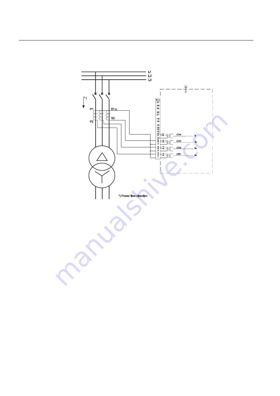
The three phase current transformers are connected to the connector X1.1 on the rear
panel. The rated currents of the measuring input are 1 A and 5 A.
Fig. 9.3.2.-1
Connection diagram for the standard configuration B01 with three
current transformers
The technical data of the current transformers are set via the Relay Setting Tool or
the local HMI. The settings can be found in
Main menu\Configuration\Meas. devices\
. Refer to
Technical
Reference Manual, General
(see Section 1.5. Related documents) for further
information about how to set the rated currents.
9.3.3.
Protection
All the necessary settings for the protection functions can be set via the Relay
Setting Tool or the local HMI. The settings can be found in
Main menu\Protection\
.
9.3.3.1.
Phase overcurrent protection
The overcurrent protection includes three stages. The relay measures the phase
currents on the HV side. The definite-time instantaneous overcurrent stage 3I>>> is
set to operate on short circuits occurring on the primary side of the transformer and
most of the transformer winding. The fault currents are limited by the impedance of
the transformer so it does not detect faults on the secondary side of the transformer.
The 3I>>> is current selective and it is set to a minimum operate time or
instantaneous.
REX 521
Cu
rrT
ra
n
s
HV
MV
Summary of Contents for REX 521
Page 1: ...Protection Relay REX 521 Technical Reference Manual Standard Configurations ...
Page 2: ......
Page 12: ...12 ...
Page 22: ...22 ...
Page 62: ...62 ...
Page 72: ...72 ...
Page 128: ...128 ...
Page 132: ...132 ...
Page 172: ...172 ...
Page 198: ...198 ...
Page 249: ......


