Installation
14
RHD8000 ... 16000 42/68-166-EN
Pos: 8.14 /Überschriften/1.1.1/1-spaltig/Wegabhängige Anschlageinstellung @ 10\mod_1181635134578_3101.doc @ 103603
3.4.2 Adjusting the stops in dependence of the travel
Pos: 8.15 /Montage/Aktorik/Elektr. Schwenkantriebe/Allgemein/Wegabhängige Anschlageinstellung @ 10\mod_1181570388312_3101.doc @ 103106
1.
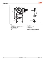
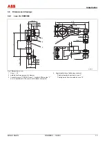
Move the output lever / valve to the position requiring fine adjustment.
2.
Put the stop onto the toothing as close to the output lever as possible and fasten it with
screws.
3.
The mechanical limit stops may not be fixed within the adjusted operating range.
4.
Move the output lever towards the stop using the handwheel; turn the coupling rod for fine
adjustment.
5.
Fasten the counter nuts.
6.
Fasten the stop in the other mounting position close to the end position, depending on the
toothing.
Pos: 8.16 /Überschriften/1.1.1/1-spaltig/Kraftabhängige Anschlageinstellung @ 10\mod_1181635174750_3101.doc @ 103626
3.4.3 Adjusting the stops in dependence of the torque
Pos: 8.17 /Montage/Aktorik/Elektr. Schwenkantriebe/Allgemein/Kraftabhängige Anschlageinstellung @ 10\mod_1181570779703_3101.doc @ 103152
1.
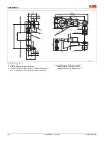
First proceed as described above for travel-dependent adjustment.
2.
Prior to re-fastening the counter-nut provide pretension in the valve’s "CLOSED" position.
3.
Lock the hand wheel.
4.
Turn the coupling tube or slightly shift the limit stops to get a small gap between lever and
limit stop.
5.
The procedure and gap size depend on the stiffness of the linkage arrangement.
6.
Tighten the counter-nuts and limit stop screws.
Pos: 8.18 /======= Seitenumbruch ======== @ 0\mod_1126532365768_3101.doc @ 3830

