background image

Trouble shooting 


32 

RHD250 ... 4000 42/68-165-EN 


Pos: 16.1 /Überschriften/1/D - F/Fehlerbehebung @ 8\mod_1177421457781_3101.doc @ 86174 


7 Trouble 

shooting 


Pos: 16.2 /Fehlermeldungen/Aktorik/Antriebe/Allgemein/Fehlersuche @ 10\mod_1181571422531_3101.doc @ 103198 


This chapter only covers failures caused by the hardware. Use the online-help of the 
configuration software for an extended troubleshooting. 

failure pattern 

possible reason 

troubleshooting 

actuator can not move the valve 

failure either at the actuator or 
at the final control element 
(e.g., stuffing box tightened too 
much) 

detach actuator from valve 
if the actuator moves the valve is the 
possible cause 
if the actuator does not run, the actuator 
is the possible cause 

incorrect electronic unit or 
incorrect data set 

Compare the nameplate data on the 
actuator and electronic unit. 

Incorrectly configured 
electronic unit  

Check/update the settings for the 
parametrization software 

no communication with the 
control system 

Check wiring 

incorrect wiring between 
actuator and electronic unit 

Check wiring 

motor / brake faulty 

Check the winding resistance of the 
motor and brakes 
Check the brake lock 

Binary inputs on the electronic 
unit are not wired 

Make connection 

actuator does not react 

Brake does not release (no 
mechanical "click") 

Check the brake air gap (approx. 
0.25 mm) and electrical connection to 
the brake 
check winding resistance of the brake 
coil 

actuator does not run in AUT 
mode, although “AUT” is 
selected in the user interface 

Binary input 1 (BE 1) not wired 

Make connection 
Check the software settings for the 
binary inputs 

LEDs in the commissioning and 
service panel (CSP) flash 
synchronously 

Actuator is not adjusted 
properly 

Adjust actuator 

LEDs flash alternately 

Electronic unit / drive failure 

failure when approaching the 
end position 

Actuator in limit range of 
positioning sensor 

drive the actuator beyond the adjusted 
end position (either manually or using 
the push buttons on the CSP); <:hr>(if 
necessary disconnect from valve or 
damper) 
drive the actuator back into the 
operating range and connect it to the 
valve / damper 
re-adjust the operating range 

Pos: 16.3 /Überschriften/1.1/1-spaltig/D - F/Elektrische Prüfwerte @ 10\mod_1181642679500_3101.doc @ 103909 


7.1 

Electrical test values 


Pos: 16.4 /Fehlermeldungen/Aktorik/Antriebe/RHD250...4000/Elektrische Prüfwerte @ 14\mod_1194261372640_3101.doc @ 135870 


MCS 071 BA 

MCS 080 BA 

MC 090 BA 

MC 100 BA 

Winding resistance ± 5 % at 20 °C (68 °F) 

motor 21 

 8 

 3,7 

 3,7 


brake 2134 

 1688 

 1630 

 1377 


Pos: 17 /=======  Seitenumbruch ======== @ 0\mod_1126532365768_3101.doc @ 3830 

Summary of Contents for RHD250

Page 1: ...N Electrical Part Turn Actuator RHD250 4000 Pos 1 Titelblätter Copyright BA IA Aktorik Antriebe Contrac RHD250 4000 Contrac 14 mod_1194246738218_3101 doc 135093 Rated torque 250 4000 Nm 200 3000 lbf ft P R O F I B U S PROCESS FIELD BUS ...

Page 2: ...ermany Tel 49 551 905 534 Fax 49 551 905 555 CCC support deapr de abb com Copyright 2008 by ABB Automation Products GmbH Subject to change without notice This document is protected by copyright It assists the user with the safe and efficient operation of the device The contents may not be copied or reproduced in whole or in excerpts without prior approval of the copyright holder Pos 3 Inhaltsverze...

Page 3: ...nformation 9 1 13 Operating safety information 10 1 14 Maintenance safety information 10 2 Design and function 11 3 Installation 12 3 1 Actuator check 12 3 2 Mounting position 12 3 3 Installation instructions 13 3 4 Assembly with the valve 13 3 4 1 Preparation 13 3 4 2 Adjusting the stops in dependence of the travel 14 3 4 3 Adjusting the stops in dependence of the torque 14 3 5 Mounting examples ...

Page 4: ...peration 28 5 1 Automatic manual mode 28 5 2 Manual operation 28 6 Maintenance 29 6 1 Inspection and overhaul 29 6 2 Brake adjustment 30 6 3 Oil change 30 6 4 Filling capacity 31 7 Trouble shooting 32 7 1 Electrical test values 32 8 Technical data 33 8 1 General information 33 8 2 Technical data RHD250 33 8 3 Technical data RHD500 RHD800 34 8 4 Technical data RHD1250 2500 34 8 5 Technical data RHD...

Page 5: ...doc 144907 The actuators are used for operating final control elements valves vanes etc They may only be operated using the appropriate Contrac electronic unit Do not use these actuators for any other purpose Otherwise a hazard of personal injury or of damage to or impairment of the operational reliability of the device may arise In addition to these operating instructions the relevant documentati...

Page 6: ...One of these symbols in conjunction with the Danger warning indicates an imminent danger If it is not avoided death or serious injury will result Warning Bodily injury The symbol in conjunction with the Warning message indicates a possibly dangerous situation If it is not avoided death or serious injury could result Caution Slight injuries The symbol in conjunction with the Caution message indicat...

Page 7: ...ssociated Contrac electronic unit 8 Free 9 Free 10 Free for customer specific entry Pos 4 13 Sicherheit Aktorik Allgemein Pflichten des Betreibers 10 mod_1181723170562_3101 doc 105157 1 5 Operator liability The operators must strictly observe the applicable national regulations in their countries with regards to installation function tests repairs and maintenance of electrical devices Pos 4 14 Sic...

Page 8: ...Through its publications ABB conducts an open dialog with the public This product solution is manufactured from materials that can be reused by specialized recycling companies 1 8 1 Information on WEEE directive 2002 96 EC Waste Electrical and Electronic Equipment This product solution is not subject to the WEEE directive 2002 96 EC and relevant national laws e g ElektroG in Germany Dispose of the...

Page 9: ...ents for positioning vanes and valves etc Only qualified specialists who have been trained for these tasks are authorized to mount and adjust the control actuator and to make the electrical connection When working on the actuator itself or the electronics always observe the locally valid accident prevention regulations and the regulations concerning the construction of technical installations The ...

Page 10: ...s which may be accessed by unauthorized persons take the required protective measures Switch off the power supply to the motor prior for manual operation Pos 4 30 Überschriften 1 1 1 spaltig S U Sicherheitshinweise zur Wartung 10 mod_1181811822343_3101 doc 106052 1 14 Maintenance safety information Pos 4 31 Sicherheit Aktorik Elektr Schwenkantriebe Allgemein Sicherheitshinweise zur Wartung 10 mod_...

Page 11: ...nzept 15 mod_1195050522390_3101 doc 140463 Functionality Compact actuator for the operation of final control elements with preferably 90 rotary movement such as flaps cocks etc The torque is transferred via a lever linkage bar assembly or the actuator is directly coupled to the cock flange A special power electronic unit controls the actuator The electronic unit serves as the interface between act...

Page 12: ... Pos 8 5 Montage Aktorik Elektr Schwenkantriebe RHD250 4000 Einbaulage Zeichnung 14 mod_1194260228968_3101 doc 135729 The spur gears of the actuator RHD250 4000 are oil lubricated They contain the max oil quantity when leaving the manufacturer Once the actuator is installed replace the uppermost check plug by the separately supplied venting plug IMB 3 IMB 6 IMB 7 IMB 8 IMV 6 IMV 5 1 2 M00366 Fig 3...

Page 13: ...en 1 1 1 spaltig V Z Zusammenbau mit dem Stellglied 10 mod_1181634985953_3101 doc 103507 3 4 Assembly with the valve Pos 8 11 Überschriften 1 1 1 1 spaltig Vorbereitung 10 mod_1181635035296_3101 doc 103530 3 4 1 Preparation Pos 8 12 Montage Aktorik Elektr Schwenkantriebe Allgemein Vorbereitung 10 mod_1181569909062_3101 doc 103083 Warning Electrical voltage risk When working on the actuator or the ...

Page 14: ... Fasten the counter nuts 6 Fasten the stop in the other mounting position close to the end position depending on the toothing Pos 8 16 Überschriften 1 1 1 1 spaltig Kraftabhängige Anschlageinstellung 10 mod_1181635174750_3101 doc 103626 3 4 3 Adjusting the stops in dependence of the torque Pos 8 17 Montage Aktorik Elektr Schwenkantriebe Allgemein Kraftabhängige Anschlageinstellung 10 mod_118157077...

Page 15: ... 670 Nm 494 Lbf ft 670 Nm 494 Lbf ft lever clamping screw tightening torque 79 Nm 58 Lbf ft 195 Nm 144 Lbf ft 390 Nm 288 Lbf ft 390 Nm 288 Lbf ft Mounting screw property class 8 8 tensile strength 12 mm 0 47 inch 18 mm 0 71 inch 20 mm 0 78 inch 20 mm 0 78 inch tensile strength 800 N mm2 116032 pounds square inch 800 N mm2 116032 pounds square inch 800 N mm2 116032 pounds square inch 800 N mm2 1160...

Page 16: ...n conditions must be observed Max perm temperature of shaft Type radial force at distance x N lbf Distance x from shaft edge mm inch axial force N lbf max output torque RHD250 1767 397 24 40 1 57 310 69 69 A short term overload up to double the rated torque is possible RHD500 7542 1695 51 35 1 38 1310 294 50 A short term overload up to double the rated torque is possible RHD800 7542 1695 51 35 1 3...

Page 17: ...observed Type bore diameter mm inch Key width mm inch Hub length mm inch Minimum yield strength of hub Rp 0 2 N mm2 pounds square inch RHD250 30 0 033 1 18 0 0013 8 0 015 0 051 0 31 0 0006 0 0020 50 1 97 320 46412 80 RHD500 50 0 039 1 97 0 0015 14 0 018 0 061 0 55 0 0007 0 0024 70 2 76 320 46412 80 RHD800 50 0 039 1 97 0 0015 14 0 018 0 061 0 55 0 0007 0 0024 70 2 76 320 46412 80 RHD1250 70 0 075 ...

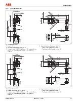
Page 18: ...wenkantrieb RHD 250 Contrac Maßbild Hebeltrieb 5 mod_1152865563125_3101 doc 34924 4 1 2 3 M00112 265 50 16 5 21 50 0 0 5 1 45 0 0 1 5 150 40 120 8 33 3 0 2 60 30 0 033 0 000 200 40 Ø18 30 74 18 23 100 120 L 220 L 18 100 120 23 99 19 Fig 6 Dimensions in mm 1 Cone 1 10 2 Welding bushings are part of shipment 3 Connection pipe 1 1 4 DIN 2440 resp 1 1 4 schedule 80 pipe size L acc to requirements The ...

Page 19: ...66 L 0 71 3 94 4 72 0 91 3 90 0 75 Fig 7 Dimensions in Inch 1 Cone 1 10 2 welding bushings are part of shipment 3 Connection pipe 1 1 4 DIN 2440 resp 1 1 4 schedule 80 pipe size L acc to requirements The pipe is not included in shipment 4 Angular deflection of ball and socket joint Pointing towards the actuator max 3 Pointing away from the actuator max 10 Pos 8 29 Seitenumbruch 0 mod_1126532365768...

Page 20: ...od_1153291203031_3101 doc 35504 M00103 1 2 3 4 L 45 14 0 018 0 061 53 8 0 2 105 120 Ø22 23 21 92 28 105 120 L 230 99 70 28 5 25 343 26 17 80 50 0 039 0 60 150 200 250 63 Ø48 Ø41 ø37 5 Fig 8 Dimensions in mm 1 Cone 1 10 2 welding bushings are part of shipment 3 Connection pipe 1 1 2 DIN 2440 resp 1 1 2 schedule 80 pipe size L acc to requirements The pipe is not included in shipment 4 Angular deflec...

Page 21: ...91 7 87 9 84 2 48 1 89 1 61 1 48 US Fig 9 Dimensions in Inch 1 Cone 1 10 2 welding bushings are part of shipment 3 Connection pipe 1 1 2 DIN 2440 resp 1 1 2 schedule 80 pipe size L acc to requirements The pipe is not included in shipment 4 Angular deflection of ball and socket joint Pointing towards the actuator max 3 Pointing away from the actuator max 10 Pos 8 32 Seitenumbruch 0 mod_112653236576...

Page 22: ...pipe 2 DIN 2440 resp 2 schedule 80 pipe size L acc to requirements The pipe is not included in shipment 4 Angular deflection of ball and socket joint Pointing towards the actuator max 3 Pointing away from the actuator max 10 4 5 L 2 95 Ø1 02 0 96 4 11 0 98 1 26 1 18 4 33 5 51 I L 9 84 4 72 2 76 7 87 2 95 9 84 11 81 13 78 18 11 4 72 3 94 0 79 Ø2 36 Ø2 07 Ø1 91US 1 38 0 030 0 001 0 0 0 0 9 0 0 0 2 9...

Page 23: ...sp 2 1 2 schedule 80 pipe size L acc to requirements The pipe is not included in shipment 4 Angular deflection of ball and socket joint Pointing towards the actuator max 3 Pointing away from the actuator max 10 4 5 3 5 6 Ø1 50 1 20 5 55 1 46 1 67 1 57 5 31 6 50 I L 11 81 L 5 51 5 51 Ø3 35 0 004 0 001 15 75 3 43 21 14 4 94 6 44 1 50 1 67 0 98 0 0 0 0 7 0 0 0 2 4 Ø2 99 Ø2 68 Ø2 28 US 0 47 1 22 5 31 ...

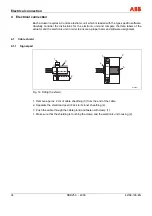
Page 24: ... and software assignment Pos 10 3 Überschriften 1 1 1 spaltig J L Kabelschirm 10 mod_1181823716656_3101 doc 106187 4 1 Cable shield Pos 10 4 Überschriften 1 1 1 1 spaltig Signalteil 10 mod_1182501083765_3101 doc 108573 4 1 1 Signal part Pos 10 5 Elektrischer Anschluss Aktorik Antriebe Allgemein Kabelschirm Anschluss 10 mod_1181823021906_3101 doc 106144 3 3 4 2 2 1 1 M00307 Fig 14 Fitting the shiel...

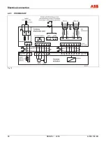
Page 25: ...BN853 Contrac EBN861 Contrac 16 mod_1197277910312_3101 doc 145230 4 2 1 Power Electronic Unit EBS853 Contrac EBS861 Contrac Pos 10 9 Technische Daten Datenblatt Aktorik Antriebe Linearantriebe Allgemein El Anschluss mit separater Elektronik EBN853 EBN861 7 mod_1172049298312_3101 doc 69413 ve 4 2 2 Analog digital Important The electrical connection is provided by a plug on the actuator and the term...

Page 26: ...Electrical connection 26 RHD250 4000 42 68 165 EN 4 2 3 PROFIBUS DP Fig 16 Pos 10 10 Seitenumbruch 0 mod_1126532365768_3101 doc 3830 ...

Page 27: ... Unit EBS852 Contrac EBS862 Contrac Pos 10 12 Technische Daten Datenblatt Aktorik Antriebe Linearantriebe Allgemein El Anschluss mit separater Elektronik EBS852 EBS862 7 mod_1174895582718_3101 doc 74303 4 2 5 Analog digital Important The electrical connection is provided by a plug on the actuator and the terminals on the electronic unit Fig 17 Pos 11 Seitenumbruch 0 mod_1126532365768_3101 doc 3830...

Page 28: ...e drive shaft Adjustable limit stops prevent overloading of the valve in the event of an operating error The motor brake locks the actuator in the current position if the power suplly is cut off Pos 12 4 Überschriften 1 1 1 spaltig G I Handradbetrieb 10 mod_1181715640046_3101 doc 104996 5 2 Manual operation Pos 12 5 Bedienung Aktorik Antriebe Schwenkantriebe Allgemein Handradbetrieb RHD 16 mod_119...

Page 29: ... 1 1 1 spaltig G I Inspektion und Überholung 10 mod_1181642170921_3101 doc 103840 6 1 Inspection and overhaul Pos 14 4 Wartung Reparatur Aktorik Antriebe Elektr Schwenkantriebe Allgemein Inspektion und Überholung RHD 16 mod_1197275309500_3101 doc 145205 Only use genuine spare parts such as ball bearings gaskets and oil may be used to overhaul the actuators Proceed acc to table when performing main...

Page 30: ... Oils for different temperature ranges may not mixed Dispose of old oil according to local regulations Make sure that the oil does not enter the water cycle Proceed as follows to drain or change the oil 1 Provide a container capable of holding the expected oil quantity acc to chapter Filling capacity 2 Open and remove the ventilation plug see Fig 3 3 Unscrew the lowermost inspection plug and drain...

Page 31: ...1 Min oil level mm under inspection plug 57 mm 1 24 inch Lower edge of upper oil plug 15 mm 2 17 inch 37 mm 1 46 inch Lower edge of upper oil plug Filling capacities RHD1250 2500 Mounting orientation IMB 3 IMB 6 IMB 7 IMB 8 IMV 5 IMV 6 Minimum oil quantity approx 29 l 7 67 gal 1 32 l 8 47 gal 1 24 l 6 35 gal 1 24 l 6 35 gal 1 33 l 8 72 gal 1 26 5 l 7 01 gal 1 Min oil level mm under inspection plug...

Page 32: ...onic unitarenotwired Makeconnection actuatordoesnotreact Brakedoesnotrelease no mechanical click Checkthebrakeairgap approx 0 25mm andelectricalconnectionto thebrake checkwindingresistanceofthebrake coil actuatordoesnotruninAUT mode although AUT is selectedintheuserinterface Binaryinput1 BE1 notwired Makeconnection Checkthesoftwaresettingsforthe binaryinputs LEDsinthecommissioningand servicepanel ...

Page 33: ... in contacts or terminals Connecting cable electronics actuator optionally see ordering information of electronics Power supply for motor and sensors Only via Contrac electronic unit see data sheet of electronic unit Pos 18 4 Überschriften 1 1 1 spaltig S U Technische Daten RHD250 14 mod_1194265807718_3101 doc 135943 8 2 Technical data RHD250 Pos 18 5 Technische Daten Datenblatt Aktorik Antriebe S...

Page 34: ...Pos 18 9 Überschriften 1 1 1 spaltig S U Technische Daten RHD1250 2500 14 mod_1194265917593_3101 doc 135989 8 4 Technical data RHD1250 2500 Pos 18 10 Technische Daten Datenblatt Aktorik Antriebe Schwenkantriebe El Schwenkantriebe RHD 1250 RHD 2500 Contrac Regelantrieb 5 mod_1153894253296_3101 doc 36093 Model RHD1250 12 RHD2500 10 RHD2500 25 Rated torque 1250 Nm 1000 lbf ft adjustable to 0 5 0 75 o...

Page 35: ...tions for short time 2 x rated torque Rated time for 90 10 900 s 40 900 s Operating speed adjustable 9 0 0 1 s 2 25 0 1 s Operating angle Typically 90 min 35 max 270 See instructions for limited operating angle if actuator is equipped with lever and limit stop Weight approx 270 kg 595 lb approx 265 kg 584 lb Related electronics For field installation For rack installation Model EBN8611 Model EBS86...

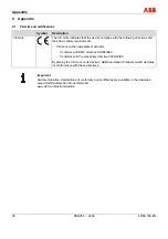
Page 36: ...th the following directives and their basic safety requirements CE mark on the nameplate of actuator Conforms with EMC directive 89 336 EEC Conforms with the machinery directive 2006 42 EC By placing the CE mark on its devices ABB Automation Products GmbH declares its conformance with these directives Pos 20 4 Anhang Aktorik Allgemein Hinweis zum Download Bereich Aktorik 10 mod_1182172251781_3101 ...

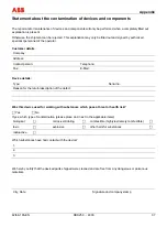
Page 37: ... person Telephone Fax E Mail Device details Type Serial no Reason for the return description of the defect Was this device used for working with substances which pose a threat or health risk F Yes F No If yes which type of contamination please place an X next to the applicable items biological F corrosive irritating F combustible highly extremely combustible F toxic F explosive F other harmful sub...

Page 38: ...ies 31 Filling capacity 31 G General information 33 General Safety Information 5 I Inspection and overhaul 29 Installation 12 Installation instructions 13 Installation position 31 Installation safety information 9 L Labels and symbols 6 Lever for RHD1250 RHD2500 22 Lever for RHD250 18 Lever for RHD4000 23 Lever RHD500 RHD800 20 M Maintenance 29 Maintenance activities 29 Maintenance intervals 29 Ma...

Page 39: ...ening torque 15 Time until next maintenance is required 29 Transport safety information 8 Trouble shooting 32 W Warranty provision 6 Wear 29 WEEE directive 8 Pos 22 4 Wechsel zwei auf einspaltig 0 mod_1130421955859_3101 doc 3829 Wechsel ein auf zweispaltig Pos 23 Rückseiten Minden_Aktorik 2 mod_1151575081640_3101 doc 32243 Ende der Stückliste ...

Page 40: ...thout notice Printed in the Fed Rep of Germany 02 2008 ABB 2008 3KXE111003R4203 42 68 165 EN Rev D ABB Limited Salterbeck Trading Estate Workington Cumbria CA14 5DS UK Tel 44 0 1946 830 611 Fax 44 0 1946 832 661 ABB Inc 125 E County Line Road Warminster PA 18974 USA Tel 1 215 674 6000 Fax 1 215 674 7183 ABB Automation Products GmbH Schillerstr 72 32425 Minden Germany Tel 49 551 905 534 Fax 49 551 ...

Reviews: