background image


ABB-free@home

®


Commissioning


Technical Manual 1473-1-8574 

18


7.2.1 

Settings of the room temperature controller 

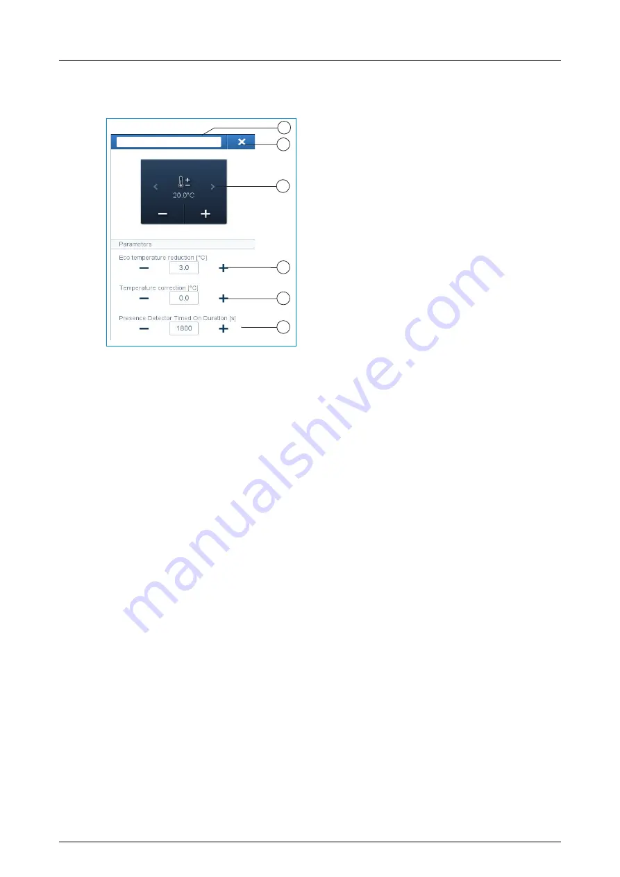
Actuator settings

[1] Changing the name 

[2] Deleting the channel via 'X' 

[3] Switching of the actuator via the button 

[4] Setting the ECO temperature reduction 

in °C - Specifying the value to which the 
temperature is reduced after the ECO 
mode is activated. 

[5] Setting the temperature correction in °C - 

Manual increase/reduction of the tempera-
ture value if the temperature is repeatedly 
not reached automatically. 

[6] Setting the switch-off delay in seconds 

during absence 
If the ECO mode is deactivated by a 
movement detector, the switch-off delay 
can be specified here when the ECO 
mode is to be re-activated after the room 
is exited. 


Other settings 

Extension unit operation - The room temperature controller can be configured in 
the device settings as extension unit. In this setting only the temperature sensor 
of the main unit is evaluated, the extension unit serves only for selecting the op-
erating mode, and the set-value temperature. 


Room Temperature Controller

Room Temperature Controller

1

4

5

6

3

2

Summary of Contents for RTC-F-1.PB

Page 1: ...1473 1 8574 14 08 2014 Technical Manual Room temperature controller RTC F 1 PB ...

Page 2: ...___________________________________ 10 5 1 Main overview _______________________________________________________________________ 10 5 2 Dimensions _________________________________________________________________________ 10 5 3 Circuit diagrams______________________________________________________________________ 10 6 Mounting _______________________________________________________________________...

Page 3: ...to persons and property and ensure reliable operation and long service life of the device Please keep this manual in a safe place If you pass the device on also include this manual Busch Jaeger accepts no liability for failure to observe the instructions in this manual If you require additional information or have questions about the device please contact Busch Jaeger or visit our Internet site at...

Page 4: ...cal instructions Warning This symbol in connection with the signal word Warning indicates a dangerous situation which could lead to immediate death or to serious injury Attention damage to property This symbol indicates a possibly damaging situation for the product Non observance can lead to damage or destruction of the product Note This symbol indicates information or references to additional use...

Page 5: ...ed use of the device The associated risk is borne exclusively by the user operator The device is not intended for the following unauthorized structural changes repairs use outdoors or in bathroom areas use with an additional bus coupler 2 4 Target group qualification of personnel Installation commissioning and maintenance of the device must only be carried out by trained and properly qualified ele...

Page 6: ...ns Disconnect the mains power supply before installation disassembly Never use the device with damaged connecting cables Do not open covers firmly bolted to the housing of the device Use the device only in a technically faultless state Do not make changes to or perform repairs on the device on its components or its accessories Keep the device away from water and wet surroundings Attention damage t...

Page 7: ...aws governing elec tronic and electrical devices and the REACH ordinance EU Directive 2002 96 EG WEEE and 2002 95 EG RoHS EU REACH Directive and Law for the Execution of the Directive EG No 1907 2006 The device contains valuable raw materials which can be recycled Used electric and electronic devices must not be disposed of with domestic waste Always dispose of the packaging material and electric ...

Page 8: ...ture controller with bus coupler is suitable for the control of conventional heating and cooling systems The devices are not pre programmed The devices must be parameterised for the use of the functions The integrated bus coupler makes possible the connection to the free home bus line 4 1 Scope of supply The scope of supply only contains the flush mounted insert 1 It must still be completed with a...

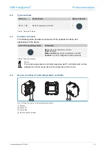
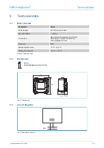
Page 9: ...Icon of the operating surface Information Name Room temperature controller Type Actuator Made available by Room temperature controller Function Controls free home heating actuators Table 2 Function overview Note The room temperature controller operates as PI controller and in time adjusts its control value also to the response of the room 4 4 Device overview of room temperature controller Fig 2 De...

Page 10: ...us subscribers 1 12mA Connection Bus connection terminal 0 4 0 8 mm Cable type J Y St Y 2x2x0 8 mm Wire stripping 6 7 mm Protection IP20 Ambient temperature 5 C 45 C Storage temperature 20 C 70 C Table 3 Technical data 5 2 Dimensions Note All dimensions are in mm Fig 3 Dimensions 5 3 Circuit diagrams Fig 4 Electrical connection 17 9 44 46 11 5 Bus ...

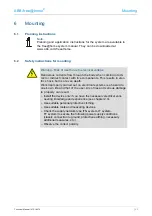
Page 11: ...onents This results in elec tric shock burns or even death Work improperly carried out on electrical systems is a hazard to one s own life and that of the user Also fires and serious damage to property can result Install the device only if you have the necessary electrical engi neering knowledge and experience see chapter 2 4 Use suitable personal protective clothing Use suitable tools and measuri...

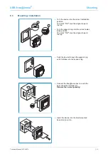
Page 12: ...ed toward the top Turn the support ring into the correct instal lation position The mark TOP must be aligned toward the top Push the device through the support ring until it latches into the support ring Connect the free home bus line with the bus connection terminal 1 Observe the correct polarity Insert the device into the flush mounted box and screw it on 1 2 ...

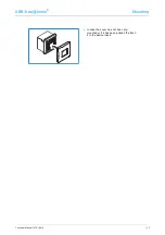
Page 13: ...ABB free home Mounting Technical Manual 1473 1 8574 13 In case the cover has not been pre mounted or if it has been pulled off attach it to the device insert ...

Page 14: ... name practical for the system Example Room temperature controller living room The devices must be parameterised for the use of the functions Commissioning of the room temperature controllers is described in the following chapters Here it is assumed that the basic commissioning steps of the overall system have already been carried out General knowledge about the Web based commissioning software of...

Page 15: ...device In the Add device bar select the desired application and pull it via drag and drop onto the floor plan in the working area Fig 6 Allocation A pop up window opens automatically which lists all the devices suitable for the application selected The desired device can be identified in 2 ways ...

Page 16: ...Identification via switching only suitable for actuators Fig 8 Identification via switching Select a device and a channel from the list Press the button in the detailed view of the device The connected load is switched Continue until you have found the device you are looking for RTC flushm Livingr L R A PMO ABB700000013 Room Temperature Controller Room Temperature Controller Room Temperature Contr...

Page 17: ...for each channel The settings are made via the allocation function of the Web based user interface of the System Access Point Device selection Fig 9 Device selection Select the device icon 1 in the floor plan of the working area view All setting options for the respective channel are displayed in the list view 2 The following settings are available 1 2 ...

Page 18: ...e if the temperature is repeatedly not reached automatically 6 Setting the switch off delay in seconds during absence If the ECO mode is deactivated by a movement detector the switch off delay can be specified here when the ECO mode is to be re activated after the room is exited Other settings Extension unit operation The room temperature controller can be configured in the device settings as exte...

Page 19: ... controller with an actuator To link the room temperature controller with an actuator first click on the desired room temperature controller 1 which is to operate the actuator and then on the actuator 2 Press the tick at the bottom right to take over your entries A blue connecting line indicates the link between the two devices The configuration is now transmitted automatically to the devices The ...

Page 20: ...ABB free home Updating options Technical Manual 1473 1 8574 20 8 Updating options A Firmware update is carried out via the Web based user interface of the System Access Point ...

Page 21: ...ler always indicates the set value temperature This can be changed via the arrow keys of the control element The room temperature controller has 4 operating modes that can be adjusted locally Comfort operation Application You are in the room for a longer period of time the comfort tempera ture is to be reached Behaviour of the RTC The display indicates the set value temperature that has been set T...

Page 22: ...ected and the window is being opened Behaviour of the RTC The display indicates antifreeze The heating valves close If the room temperature drops below 7 C the heating is switched on again to prevent damage to the building Heating cooling switchover The room temperature controller is suitable both for heating and cooling opera tion The switchover of the two modes is made via a binary input which h...

Page 23: ...n display of set point temperature 2 Controller Off 3 Heating active 4 Cooling active 5 Frost protection active 6 Eco mode indication ECO 7 Display of comfort mode heating 8 Display of comfort mode cooling 9 Display of ECO mode 10 Display of OFF mode 11 Display of antifreeze mode 6 OFF 2 3 4 5 1 6 7 8 9 10 11 ...

Page 24: ...irs Once the device is opened the warranty is void Access to the device must be guaranteed for operation testing inspection maintenance and repairs according to DIN VDE 0100 520 10 1 Cleaning Dirty units can be cleaned with a dry cloth If this is not sufficient a cloth slightly moistened with a soap solution can be used Caustic cleaning agents or solvents must not be used ...

Page 25: ...ges as well as changes to the contents of this document without prior notice The detailed specifications agreed upon apply for orders ABB accepts no responsibility for possible errors or incompleteness in this document We reserve all rights to this docu ment and the topics and illustrations contained therein The document and its contents or extracts thereof must not be reproduced transmitted or re...

Reviews: