background image

INSTRUCTION HANDBOOK

1SDH002303A1001 - ECN000285442

EMAX 2 E1.2

Disassembly instructions

Summary of Contents for SACE Emax 2 E1.2

Page 1: ... INSTRUCTION HANDBOOK 1SDH002303A1001 ECN000285442 EMAX 2 E1 2 Disassembly instructions ...

Page 2: ......

Page 3: ...ng with any disassembly operation it s mandatory to put the circuit breaker in open position and make sure that the springs of the operating mechanism are discharged Disassembly operations of circuit breakers must be performed by qualified and skilled personnel in the electrical field IEV 195 04 01 person with relevant education and experience to enable him or her to perceive risks and to avoid ha...

Page 4: ...On the trip unit 1 Protections Mounted on the back part of the circuit breaker 6 Motor PCS support Mounted on the left part of the circuit breaker 1 Microswitch support Mounted on the left part of the circuit breaker 1 S51 signal Mounted on the left part of the circuit breaker 1 Trip coil In the trip coil group 1 Trip coil group Mounted on the left part of the circuit breaker 1 Connector On the MI...

Page 5: ...ting from original installation For each phase following information is provided Part parts to be disassembled title of the phase Tools to be used Description of actions to be performed Pictures showing actions to be performed List quantity and picture of disassembled parts with an indication about separate treatment when applicable In case of potential hazards signal below is reported ...

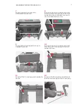
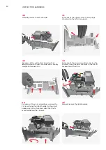
Page 6: ...pper part of the circuit breaker fixing the circuit breaker front cover to the circuit breaker main structure 2 By means of the cross screwdriver unscrew the 3 screws fixing the cover 4 Lift the spring charging lever and by means of the cross screwdriver unscrew the screw located below the springs charging lever fixing the circuit breaker cover to the circuit breaker main structure 6 By means of t...

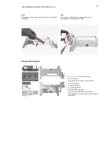
Page 7: ...lever from the reset support of the T U reset group 9 Manually lift the circuit breaker front cover to complete the removal 8 By means of the cross screwdriver unscrew the 2 screws located in the lower part of the circuit breaker fixing the circuit breaker front cover to the circuit breaker main structure 10 By means of the cross screwdriver unscrew the screw fixing the T U reset group to the circ...

Page 8: ...cross screwdriver unscrew the 2 screws located in the lower part of the operating mechanism cover fixing the operating mechanism cover to the circuit breaker main structure 15 Manually remove the reset spring from the lever support 14 Manually remove the spring from the lever 16 By means of the tork key remove the screw fixing the operation counter cap to the circuit breaker front cover and after ...

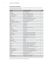
Page 9: ... transparent protection Plastic 1 cover Plastic 1 withdrawable terminals cover Plastic 3 1 2 2 2 1 1 2 screws Metal 1 reset lever Plastic 1 lever Plastic SEPARATE TREATMENT Thermoplastics containing brominated flame retardants 1 spring Metal 1 lever support Plastic SEPARATE TREATMENT Thermoplastics containing brominated flame retardants 1 spring reset Metal 2 screws and related washers Metal 1 cir...

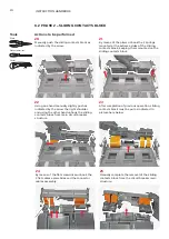
Page 10: ...rcuit breaker structure 24 By means of the flat screwdriver unhook the 3 flat cables assemblies and the connector cables assembly 21 By means of the pliers unhook the 2 springs mounted at the extreme sides of the sliding contacts block keeping them mounted on the sliding contacts block 23 After completion of previous operation sliding contacts block must be put as indicated in picture here below 2...

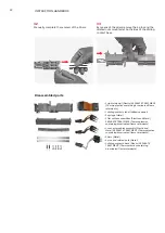
Page 11: ... the 3 flat cables assemblies and of the connector cables assembly manually pulling them 31 By means of the flat screwdriver push as indicated by the arrow the 2 bars mounted inside the sliding contacts block 28 By means of the cutter start removing the sliding contacts label located on the right side wall and manually complete the operation 27 Manually complete the removal of the right side wall ...

Page 12: ...ining brominated flame retardants 1 sliding contacts label Adhesive paper 2 springs Metal 3 flat cables assemblies Plastic and Metal SEPARATE TREATMENT Thermoplastics containing brominated flame retardants 1 connector cables assembly Plastic and Metal SEPARATE TREATMENT Thermoplastics containing brominated flame retardants 2 bars Metal 4 pins and related nuts Metal 1 sliding contacts base Plastic ...

Page 13: ...er to the circuit breaker main structure 38 By means of the cross screwdriver unscrew the 2 screws fixing the left shoulder to the circuit breaker main structure 35 Manually complete the removal of the cover 37 Manually complete the removal of the withdrawable terminals cover 39 By means of the cross screwdriver unscrew the 2 screws fixing the left shoulder to the circuit breaker main structure an...

Page 14: ...the 2 nuts mounted behind the 2 screws 45 Manually remove the right shoulder 42 By means of the cutter start removing the 3 labels located on the left shoulder and manually complete the operation 41 By means of the pliers remove the 2 springs mounted on the left side support 43 By means of the cross screwdriver unscrew the 2 screws fixing the right shoulder to the circuit breaker main structure ...

Page 15: ... pliers remove the spring mounted on the right shoulder Disassembled parts 2 2 2 2 2 2 screws Metal 1 cover Plastic 1 withdrawable terminals cover Plastic 2 2 nuts Metal 2 shoulders Metal 2 1 springs Metal 3 labels Adhesive paper 1 slide Plastic SEPARATE TREATMENT Thermoplastics containing brominated flame retardants ...

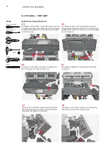
Page 16: ...hite connector from the trip unit 52 By means of the flat screwdriver unhook the cable protection from the trip unit and after manually complete the removal 49 By means of the cross screwdriver unscrew the 2 screws located on the front of the circuit breaker fixing the trip unt to the circuit breaker main structure 51 Manually complete the removal of the white connector 53 By means of the flat scr...

Page 17: ...nd manually complete the removal operation 58 Manually remove the plug mounted on the left part of the trip unit 56 By means of the scissors cut the cabling completing the removal of the trip unit from the circuit breaker main structure 55 Manually unhook the last cabling connecting the trip unit to the circuit breaker main structure 57 By means of the torx key unscrew the 4 screws fixing the 2 pl...

Page 18: ...p unit 62 By means of the cutter start removing the label located on the front of the rating plug case and by means of the pliers complete the operation 61 Manually push the rating plug case appendix as indicated by the arrow and by means of the pliers remove the rating plug printed circuit board 63 By means of the cutter start removing the rating plug data matrix label located on the rating plug ...

Page 19: ... the trip unit main structure 70 Manually remove the printed circuit board from the Ekip measuring blind cover 68 By means of the torx key unscrew the 2 screws fixing the Ekip measuring blind case to the Ekip measuring blind cover 67 By means of the cutter start removing the data matrix label located in the back part of the Ekip measuring blind plug and by means of the pliers complete the operatio...

Page 20: ... screwdriver unhook the HMI box from the display 76 Manually remove the battery 74 By means of the cutter start removing the trip unit front label and by means of the pliers complete the operation 73 Manually complete the removal of the display 75 By means of the flat screwdriver remove the battery cover on the right side of the display ...

Page 21: ...d from the display support 82 Manually remove the battery gasket 80 Manually separate the display and the HMI LCD cover 79 By means of the cutter start removing the 2 data matrix labels located in the back part of the HMI box and by means of the pliers complete the operation 81 By means of the flat screwdriver remove the i TEST pushbutton from the HMI LCD cover ...

Page 22: ...xing the trip unit case to the trip unit back cover 88 Manually complete the removal of the backplane 86 Manually separate the gasket from the display 85 Manually separate the display from its printed circuit board 87 By means of the torx key unscrew the 4 screws fixing the backplane to the trip unit main structure ...

Page 23: ...By means of the flat screwdriver push as indicated by the arrow the cables and manually remove them 94 Manually complete the removal of the trip unit printed circuit board 92 Manually complete the removal of the trip unit back cover 91 By means of the flat screwdriver unhook the trip unit case from the trip unit back cover 93 By means of the flat screwdriver unhook the trip unit printed circuit bo...

Page 24: ...c 1 trip unit front label Adhesive paper 1 battery cover Plastic SEPARATE TREATMENT Thermoplastics containing brominated flame retardants 1 battery Battery SEPARATE TREATMENT Battery 1 HMI LCD cover Plastic 1 i Test pushbutton Rubber 1 battery gasket Rubber 1 display support Plastic 1 display printed circuit board Plastic Metal and Electronic components SEPARATE TREATMENT Printed circuit board 1 d...

Page 25: ...ircuit breaker main structure 99 Manually separate the terminals from their protections 98 Push as indicated by the arrow the terminals and the related protections and manually remove the 2 parts Actions to be performed Allen key 8mm 12 screws and related washers Metal 6 terminals Metal 6 protections Plastic SEPARATE TREATMENT Thermoplastics containing brominated flame retardants ...

Page 26: ...e screws fixing the claw contacts to the circuit breaker main structure 99 UL Manually separate the claw contacts from their protections 98 UL Push as indicated by the arrow the claw contacts and the related protections and manually remove the 2 parts Actions to be performed Disassembled parts 12 screws and related washers Metal 6 claw contacts Metal 6 protections Plastic SEPARATE TREATMENT Thermo...

Page 27: ...e 102 Manually complete the removal of the motor PCS support from the circuit breaker main structure 104 Manually separate the the PCS cover and the motor PCS support 101 By means of the flat screwdriver slightly push the appendix as indicated by the arrow in order to unhook the microswitch and after manually remove the microswitch support 103 By means of the torx key unscrew the screw fixing the ...

Page 28: ... push the lower plate as indicated by the arrow in order to complete the removal 110 By means of the cross screwdriver unscrew the screw fixing the lower plate to the trip coil 108 By means of the flat screwdriver lift the trip coil group 107 By means of the flat screwdriver unhook the connector from the trip coil group 109 Manually remove the trip coil group ...

Page 29: ...s SEPARATE TREATMENT Printed circuit board 1 microswitch support Plastic SEPARATE TREATMENT Thermoplastics containing brominated flame retardants 1 S51 signal Plastic and Metal SEPARATE TREATMENT Thermoplastics containing brominated flame retardants 1 lower plate Metal 1 trip coil Plastic Metal and Magnets SEPARATE TREATMENT Magnets 1 trip coil group Plastic and Metal SEPARATE TREATMENT Thermoplas...

Page 30: ...r the MID to the operating mechanism 115 Manually remove the support key block 117 Manually lift and remove the shunt opening release plug 114 By means of the allen key unscrew the 2 screws fixing the support key block over the MID to the operating mechanism 116 Manually remove the key lock support present below the support key block 118 Manually remove the connector located in the upper part of t...

Page 31: ...cross screwdriver unscrew the screw fixing the microswitch I O assembly to the MID 123 Manually remove the MID 121 By means of the flat screwdriver remove the benzing mounted on the lever present on the right side of the operating mechanism 120 By means of the cross screwdriver unscrew the 4 screws fixing the MID to the circuit breaker main structure 122 Manually remove the lever pulling it as ind...

Page 32: ...ires cover and the wiring 129 By means of the cross screwdriver unscrew the screw fixing the wires cover to the circuit breaker main structure 127 Manually remove the printed circuit board 126 By means of the flat screwdriver unhook the printed circuit board mounted inside the microswitch I O assembly 128 Manually remove the auxiliary contacts lever mounted on the MID ...

Page 33: ...benzing Metal 1 lever Plastic 1 microswitch I O printed circuit board Plastic Metal and Electronic components SEPARATE TREATMENT Printed circuit board 1 microswitch I O assembly support Plastic SEPARATE TREATMENT Thermoplastics containing brominated flame retardants 1 MID Plastic Metal and Electronic components SEPARATE TREATMENT Printed circuit board 1 auxiliary contact lever Metal 1 wires cover ...

Page 34: ... means of the cutter start removing the protection plate located on the right side of circuit breaker and manually complete the operation 132 By means of the cutter start removing the protection plate located on the left side of circuit breaker and manually complete the operation 134 Manually remove the open lever and the withdrawable pin located on the right side of the circuit breaker 136 Manual...

Page 35: ...e located in the place where the 2 screws had been unscrewed at step before 139 By means of the flat screwdriver push the shaft support as indicated by the arrow 138 By means of the allen key unscrew the 2 screws located on the left side of the operating mechanism 140 By means of the allen key unscrew the 2 screws located on the right side of the operating mechanism ...

Page 36: ...by the arrow until the pin comes out from the hole left by the cover cap on the right side of the circuit breaker and after remove the rod 147 Push down the rod using the hammer 145 By means of the flat screwdriver push the shaft support as indicated by the arrow 144 Manually remove the RTC lever 146 Put the circuit breaker with the left side up and insert the rod in the hole left by the cover cap...

Page 37: ...er main structure 153 By means of the torx key size 10 unscrew the 3 screws fixing the wires 151 By means of the flat screwdriver remove the rear plate mounted on the upper part of the circuit breaker 150 By means of the torx key size 6 unscrew the 9 screws fixing the 2 rear plates mounted on the back part of the circuit breaker 152 Manually remove the rear plate mounted on the lower part of the c...

Page 38: ... By means of the torx key size 25 unscrew the 2 screws located in the back part of the circuit breaker 157 By means of the torx key size 20 unscrew the 6 screws located in the back part of the circuit breaker 156 By means of the torx key size 25 unscrew the 6 screws located in the back part of the circuit breaker 158 Manually remove the upper case assembly ...

Page 39: ... operating mechanism and to manage the assembly with the maximum level of attention during disassembly and dismantle phases 163 By means of the flat screwdriver unhook the 2 benzings fixing the springs charging lever to the operating mechanism 162 Manually remove the 2 unlocking shafts mounted on the pin of the operating mechanism 164 Manually remove the springs charging lever 166 Manually remove ...

Page 40: ... upper case assembly Plastic and Metal 3 wires Plastic and Metal 1 conduit Thermoplastic SEPARATE TREATMENT Thermoplastics containing brominated flame retardants 1 operating mechanism Plastic and Metal SEPARATE TREATMENT Thermoplastics containing brominated flame retardants 3 arching chambers Plastic and Metal 2 unlocking shafts Plastic SEPARATE TREATMENT Thermoplastics containing brominated flame...

Page 41: ...ed contacts Plastic and Metal 1 upper case assembly Plastic Flat screwdriver Tools Actions to be performed 6 9 PHASE 9 UPPER CASE ASSEMBLY AND UPPER FIXED CONTACTS 167 Manually remove the 2 protections located in the upper part of the upper case assembly 169 By means of the flat screwdriver remove the plastic part from the upper fixed contacts 168 By means of the allen key unscrew the 6 screws fix...

Page 42: ...screws fixing the fixed contacts to the lower case assembly and after manually complete the removal operation 174 Manually remove the sensors 171 By means of the allen key unscrew the 6 screws located in the back part of the lower case assembly 173 Manually push the cover mounted below the sensors as indicated by the arrow 175 By means of the flat screwdriver lift the moving contacts assembly unti...

Page 43: ... 6 screws and related washers Metal 3 fixed contacts Metal 3 covers Plastic SEPARATE TREATMENT Thermoplastics containing bromintated flame retardants 3 sensors Plastic and Mixture SEPARATE TREATMENT Thermoplastics containing bromintated flame retardants 1 moving contacts assembly Plastic and Metal 3 insulation protections Thermoplastic rubber SEPARATE TREATMENT Thermoplastics containing bromintate...

Page 44: ...ocated on the right side of the circuit breaker cover and manually complete the operation 179 Manually complete the removal of the command protection 181 By means of the flat screwdriver remove the plug from the circuit breaker cover Actions to be performed Disassembled parts 1 screw Metal 1 command protection Metal 1 label Adhesive paper 1 plug Plastic 1 circuit breaker cover Plastic Torx key Cut...

Page 45: ...y instruction EMAX 2 E1 2 7 ENERGY CONSUMPTION FOR CIRCUIT BREAKERS DISASSEMBLY Since all disassembly operations illustrated in this document are manual the CO2 equivalent emissions can be considered null negligible ...

Page 46: ...46 INSTRUCTION HANDBOOK ...

Page 47: ...47 Disassembly instruction EMAX 2 E1 2 ...

Page 48: ... Copyright 2022 ABB All rights reserved Specifications subject to change without notice ABB SACE A division of ABB S p A L V Breakers Via Pescaria 5 24123 Bergamo Italy Phone 39 035 395 111 Fax 39 035 395 306 433 abb it lowvoltage ...

Reviews: