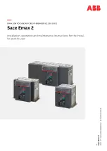
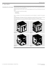
background image

SACE Emax 2

DOC. N° 1SDH001000R0002 - ECN000297030

EN

EMAX LOW VOLTAGE AIR CIRCUIT-BREAKERS E2.2-E4.2-E6.2

Sace Emax 2

Installation, operation and maintenance instructions for the instal-
ler and the user

Sac

e Ema

x 2

DOC

. N° 1SDH001

000R0002 - ECN00029

70

30

Summary of Contents for SACE Emax 2 E2.2

Page 1: ...01000R0002 ECN000297030 EN EMAX LOW VOLTAGE AIR CIRCUIT BREAKERS E2 2 E4 2 E6 2 Sace Emax 2 Installation operation and maintenance instructions for the instal ler and the user Sace Emax 2 DOC N 1SDH00...

Page 2: ...ABB SACE Emax 2 ABB SACE Emax 2 2023 ABB 1SDH001000R0002 ECN000297030...

Page 3: ...andling 10 3 Description 13 4 Environmental conditions 23 5 Installation 23 Ekip Dip 31 1 General characteristics 31 2 Operator interface 32 3 Protections Introduction 34 4 List of alarms and signals...

Page 4: ...2 2023 ABB SACE Emax 2 1SDH001000R0002 ECN000297030...

Page 5: ...Trip unit SACE Emax 2 CBs equipped with dip switch type interface Trip coil CB opening actuator controlled directly by Trip unit TRIP Concluding action of protection timing or a test command which ex...

Page 6: ...ricity can create Trained Persons in the electrical field IEV 195 04 02 person adequately advised or supervised by electrically skilled persons to enable him or her to perceive risks and to avoid dang...

Page 7: ...nst certain methods installation operation and maintenance that could cause injury to personnel damage equipment or make them unsafe thesewarningsandalarmsdonotincludealltheconceivablemethodsofperform...

Page 8: ...ng international standards IEC 60947 EN 60947 CEI EN 60947 IEC 61000 UL 1066 They comply with the following EC directives Low Voltage Directives LVD No 2006 95 EC Electromagnetic Compatibility Directi...

Page 9: ...I IV Fs III IV Fs E2 2 46 Kg 101 lbs 58 Kg 128 lbs 53 Kg 117 lbs 60 Kg 132 lbs 41 Kg 90 lbs 49 Kg 108 lbs E4 2 63 Kg 139 lbs 77 Kg 170 lbs 67 Kg 148 lbs 81 Kg 179 lbs 57 Kg 126 lbs 69 Kg 152 lbs E6 2...

Page 10: ...aker serial number 6 Features of the circuit breaker Packaging checks Examine the state of the material received and verify that The circuit breaker or the fixed part are consistent with the order The...

Page 11: ...rage that The circuit breaker is in the open position and the springs are discharged See the chapter Description circuit breaker opening closing operations on page 16 The circuit breaker is protected...

Page 12: ...breaker safely refer to the instruction sheet in the zipped packaging pouch The following is the procedure for opening the packaging 1 Cut the bands that wrap the packing box See Figure 6 and Figure 7...

Page 13: ...ws and the mounting brackets See Figure 11 Moving part IEC Figure 12 Moving part UL Figure 13 Fixed part IEC and Figure 14 Fixed part UL Figure 10 Fixed circuit breaker Figure 11 Moving part IEC Figur...

Page 14: ...lbs NOTE the weights indicated in the table refer to the basic circuit breakers including relays and its sensors without terminals and without accessories the weights of the withdrawable circuit brea...

Page 15: ...nt transformer of its own phase The circuit breaker is available in two types fixed version withdrawable The circuit breaker in fixed version see Figure 18 has its own terminals for connection to the...

Page 16: ...ipped TU 7 Closing pushbutton 8 Springs charged discharged signalling device 9 Electrical data plate Description of electrical data plate IEC 1 9 10 4 5 11 8 7 2 3 12 6 13 Uimp 12 kV Figure 23 Pos Des...

Page 17: ...a ge V 254 635 Ra t e d S hor t Cir c ui t kA 100 85 S hor t Time kA Accessories AUX 4 AUX 6 RT C YR YC2 U 3 A 400 V AC 220 V 250 V AC DC 220 V 250 V AC DC 220 V 250 V AC DC 508 100 Low Vol tage AC P...

Page 18: ...s charged signalling device B is yellow CHARGED SPRING as indicated in Figure 26 Figure 25 A B Figure 26 3 Check that the circuit breaker is open open closed signalling device O OPEN and check that th...

Page 19: ...to close see Figure 35 This state occurs when after closing see step 4 Manual operations for opening and closing the circuit breaker the springs are recharged manually or automatically by the gearmot...

Page 20: ...remove all equipment used during the work and remove processing waste and materials used 1 Turn plate through 90 before inserting the moving part CLICK 1 2 3 Figure 37 2 Position the lifting plates on...

Page 21: ...latch the tongue and remove the lifting plates from the moving part See Figure 41 1 2 3 Figure 41 6 Make sure that the signalling device indicates the DISCONNECT position See Figure 42 Figure 42 7 Gri...

Page 22: ...his phase the moving part will still be in the DISCONNECT position See Figure 45 Figure 44 2 1 Figure 45 10 Turn the crank clockwise until the pushbutton comes out and the indicator shows that the cir...

Page 23: ...rder to be able to reach the test position On the UL version the fail safe prevents the removal of the circuit breaker from the fixed part with springs charged Discharge the springs before removing th...

Page 24: ...part make sure that both guides on the fixed part travel to the same extent thereby keeping the moving part parallel to the fixed part See Figure 51 Mechanical position indicators The following are th...

Page 25: ...arge of handling and lifting must use appropriate safety equipment Mounting of the fixed circuit breaker Fix the circuit breaker to a horizontal surface using 4 x M10 screws Lock the screws with tight...

Page 26: ...E6 2 circuit breakers can only be installed in vertical position Lateral fixing only for circuit breakers to IEC 60068 2 6 Test Fc standards Further details about lateral fixing of fixed parts are ava...

Page 27: ...bility The table of terminals available for each circuit breaker is given below F HR VR SHR SVR FL E2 2 IEC 690 V F W X X X X X 800 900 V X X X 1000 1150 V X UL 600 V X X E4 2 IEC 690 V X X X 800 900V...

Page 28: ...E4 2 E6 2 Phase separators Phase barriers are mandatory for 2ps configuration For the 4ps configuration it is possible to place isolation barriers for the segregation of live parts In addition the pha...

Page 29: ...0 6 100x10 1 values for spread terminals circuit breaker UL 1066 Iu A Horizontal terminals Vertical terminals Q ty Dimension of busbars in Q ty Dimension of busbars in E2 2 A 1600 3 1 4 x 2 5 2 1 4 x...

Page 30: ...SDH001060R0100 E6 2 III IV Fixed HR IEC 1SDH001060R0101 E6 2 III IV Fixed VR IEC 1SDH001060R0102 E6 2 IV FS Fixed HR VR IEC 1SDH001060R0104 E6 2 III IV Fixed F IEC 1SDH001060R0105 E6 2 III IV Withdraw...

Page 31: ...type and the peak current 100 3 94 150 5 91 200 7 87 250 9 84 300 11 81 350 13 78 400 15 75 450 17 72 500 19 69 40 60 80 100 120 140 160 180 200 220 240 260 280 300 E2 2 E4 2 E6 2 L mm 1 Ipk kA 2 Fig...

Page 32: ...kers in fixed version and the fixed part of withdrawable circuit breakers are equipped with a screw for the ground connection The connection must be implemented by means of a conductor of suitable cro...

Page 33: ...s Parameter Rated operating range Primary current 0 004 16 In 1 Rated frequency 45 55 Hz with fn 50 Hz 54 66 Hz with fn 60 Hz Peak factor Complying with standard IEC 60947 2 1 range with reference to...

Page 34: ...n LED alarm and trip B L Protection LED pre alarm C S Protection LED alarm and trip D I Protection LED trip E G Protection LED alarm and trip F Power on LED trip unit powered and on G Protections thre...

Page 35: ...able Neutral allows activation and adjustment of the protections on the neutral pole Frequency allows the selection of the installation frequency iTest pushbutton The iTest pushbutton is useful for th...

Page 36: ...versions of the trip unit When the activation threshold is exceeded the protection trips in a time that decreases as the current read increases Parameters All the parameters that can be modified by th...

Page 37: ...Threshold I2 It defines the current value that activates the protection when exceeded with reference to the curve it is the part parallel to the y axis IMPORTANT The I2 threshold set must be higher t...

Page 38: ...adjustable time Parameters The user can set the intervention threshold Parameter Description Enable By setting the threshold dip switches to the Off position the protection is disabled Threshold I3 I...

Page 39: ...ding to the selection NOTE calculation of the tripping time of the inverse time curve is based on a mathematical expression The details are provided in the table on page39 Threshold I4 It defines the...

Page 40: ...on the Neutral is disabled Threshold InN It establishes the multiplication factor applied to the trip thresholds of the protections 50 trip threshold of the neutral current lower than other phases 10...

Page 41: ...Iinst Defined by ABB Instantaneous 1 See the serigraph for the available combinations 2 t t calculation is valid for If values that have exceeded the trip threshold of the protection Use fault curren...

Page 42: ...R single G All R G G G Internal configuration error 5 x x x A Trip coil disconnected or trip command failed x B Current sensors disconnected x B Rating Plug error X B E Protection delay x C Temperatur...

Page 43: ...n for all other sizes in the absence of auxiliary power supply t2 0 4s in the case of UL circuit breaker t4 0 4s in the case of UL circuit breaker I4 1200 A in case of UL circuit breaker E Install by...

Page 44: ...l YO 4 YC R R YO2 4 R R YU 2 4 R R M R R YR R Security mechanical KLC PLC R R KLP PLP 1 R R SL 1 S S DLC R R Anti insertion lock S S MOC R R FAIL SAFE 3 R R Protection mechanical PBC R R IP54 R R HTC...

Page 45: ...r HAZARD RISKOFELECTRICSHOCK Testthecircuit breakerwithallswitchgearapparatus de energized IMPORTANT The verifications involve procedures which must only be performed by persons skilled in the electri...

Page 46: ...the presence of an undervoltage coil the circuit breaker can be closed only after the trip unit is energized Trip unit alarm Connect the protection device Ekip TT to the trip unit and verify that ther...

Page 47: ...The circuit breaker closes correctly the signals are normal 2 Turn off the voltage supply to the trip unit The circuit breaker opens 3 Power the undervoltage coil at the relevant rated voltage and per...

Page 48: ...acked 1 Perform operating tests Result the interlocks function correctly Racking in out device 1 Perform a few racking in and racking out operations Result in the rack in operation the circuit breaker...

Page 49: ...dures and checked the accessories Print this sheet and use it to make an inspection report in the Checks column Operation Description Check 1 Circuit breaker OFF Open the circuit breaker 2 Circuit bre...

Page 50: ...EV 195 04 01 person with sufficient training and experience to enable him or her to perceive risks and to avoid the dangers potentially created by electricity This is because it may be necessary to pe...

Page 51: ...set Press the TU Reset button The power supply voltage of the auxiliary circuits is too low Measure the voltage it should not be lower than 70 of the rated voltage of the coil The power supply voltage...

Page 52: ...y in the terminals Make sure there is continuity between cable and terminal and if necessary reconnect the cables of the gearmotor to the terminals The connections of the power supply circuit are wron...

Page 53: ...le it if it is not necessary Incorrect neutral selection Modify the neutral selection Rapid trip with I3 Off linst trip Correct operating condition with short circuit at high current High ground fault...

Page 54: ...forming procedures that can be performed by Trained Persons in the electrical field IEV 195 04 02 person adequately advised or supervised by electrically skilled persons to enable him or her to percei...

Page 55: ...ABB SACE Emax 2 Putting into service and maintenance 4 Decommissioning and treatment at end of life 53 2023 ABB 1SDH001000R0002 ECN000297030...

Page 56: ...ity whatsoever for potential errors or possible lack of information in this document We reserve all rights in this document and in the subject matter and illustrations contained therein Any reproducti...

Reviews: