

ABB | SACE Emax 2
ABB | SACE Emax 2
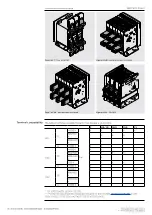
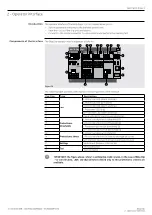
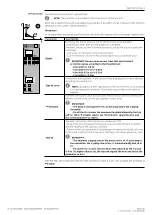
Ekip Dip
39 | © 2023 ABB | 1SDH001000R0002 - ECN000297030
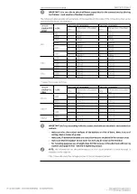
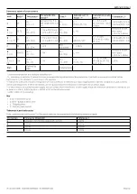
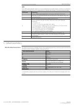
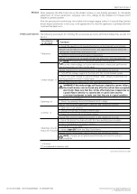
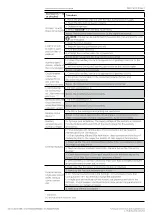
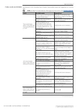
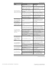
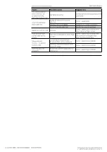
Summary table of protections
ABB
ANSI
(5)
Threshold
(1)
Threshold tole-
rance
(3)
Time
(1)
Calculation for-
mula t
t
(2)
Calculation exam-
ple t
t
(2)
Tolerance t
t
(3)
L
49
I1 =
0.4…1 In
activation for If in
the range (1.05...1.2)
x I1
t1 =
3…144 s
t
t
=
(9 t1) / (If / I1)
2
t
t
= 6.75 s with:
I1 = 0.4 In; t1 = 3 s; If
= 0.8 In
± 10 % with If ≤ 6 In
± 20 % with If > 6 In
S
(t = k)
50 TD
I2 =
0.6...10 In
± 7 % with If ≤ 6 In
± 10 % with If > 6 In
t2 =
0.1…0.8 s
t
t
= t2
-
The better of the
two values:
± 10 % or ± 40 ms
S
(t = k / l
2
)
51
I2 =
0.6...10 In
± 7 % with If ≤ 6 In
± 10 % with If > 6 In
t2 =
0.1…0.8 s
t
t
=
(100 t2) / (If)
2
t
t
= 5 s con:
I2 = 1 In; t2 = 0.8 s;
If = 4 In
± 15 % with If ≤ 6 In
± 20 % with If > 6 In
I
50
I3 =
1.5...15 In
± 10 %
Not
adjustable
t
t
≤ 30 ms
-
-
G
(t = k)
50N TD
I4
(4)
=
0.1...1 In
± 7 %
t4 =
0.1…0.8 s
t
t
= t4
-
The better of the
two values:
± 10 % or ± 40 ms
G
(t = k /
l
2
)
51N
I4
(4)
=
0.1...1 In
± 7 %
t4 =
0.1…0.8 s
t
t
=
2 / (If / I4)
2
t
t
= 0.32 s with:
I4 = 0.8 In; t4 = 0.2
s; If = 2 In
± 15 %
Iinst
-
Defined by
ABB
-
Instantaneous -
-
-
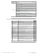
(1)
See the serigraph for the available combinations.
(2)
t
t
calculation is valid for If values that have exceeded the trip threshold of the protection. Use fault current and threshold values
expressed in In to calculate t
t
, as shown in the example.
(3)
Tolerances valid with trip unit energized in service conditions or with the auxiliary; tripping time ≥ 100 ms, temperature and currents
within operating limits. If these conditions are not guaranteed, the tolerances in the table shown below apply.
(4)
In the presence of auxiliary power supply, you can select all the thresholds. In self-supply mode the minimum threshold is limited to: 0.3
In (with In = 100 A), 0.25 In (with In = 400 A) or 0.2 In (for all other sizes).
(5)
ANSI / IEEE C37-2 encoding.
Key
• (t=k) - Fixed time curve
•
(t=k/I
2
) - Dynamic time curve
•
t
t
- Tripping time
•
If - Primary fault current
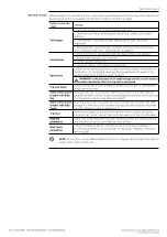
Tolerances in particular cases
If the conditions defined in point
(3)
of the above table are not guaranteed, the following tolerances apply:
Protection
Tolerance threshold
Tolerance t
t
L
Activation for If in the range (1.05...1.2) x I1
± 20 %
S
± 10 %
± 20 %
I
± 15 %
≤ 60 ms
G
± 15 %
± 20 %


