
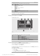


ABB | SACE Emax 2
Ekip Touch protection trip unit | 2 - Pages details
9 | © 2018 ABB | 1SDH001316R0002 - ECN000086018 - Rev. C
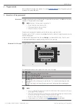
2 - Pages details
Details related to this chapter are available in the manual
available on the website ABB library.
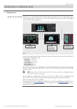
3 - Insertion of the password
Description
The page where the password is entered is open, if a parameter to be entered, or the
Test
menu have been
selected, or if the password must be changed.
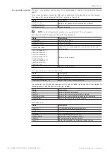
NOTE:
insertion of the password is requested, if:
•
The password has never been inserted.
•
After programming has been cancelled.
•
After a few minutes of inactivity.
The password is composed of five digits, each of which can have a value from 0 to 9.
The default value is “00001”, and it must be modified after the first switch-on in order to prevent access by
unauthorized personnel.
In order to modify the password, from the menu
Settings
, you need to select
System
-
New Password.
It is possible to disable the password by inserting "00000" as new password .
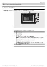
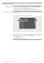
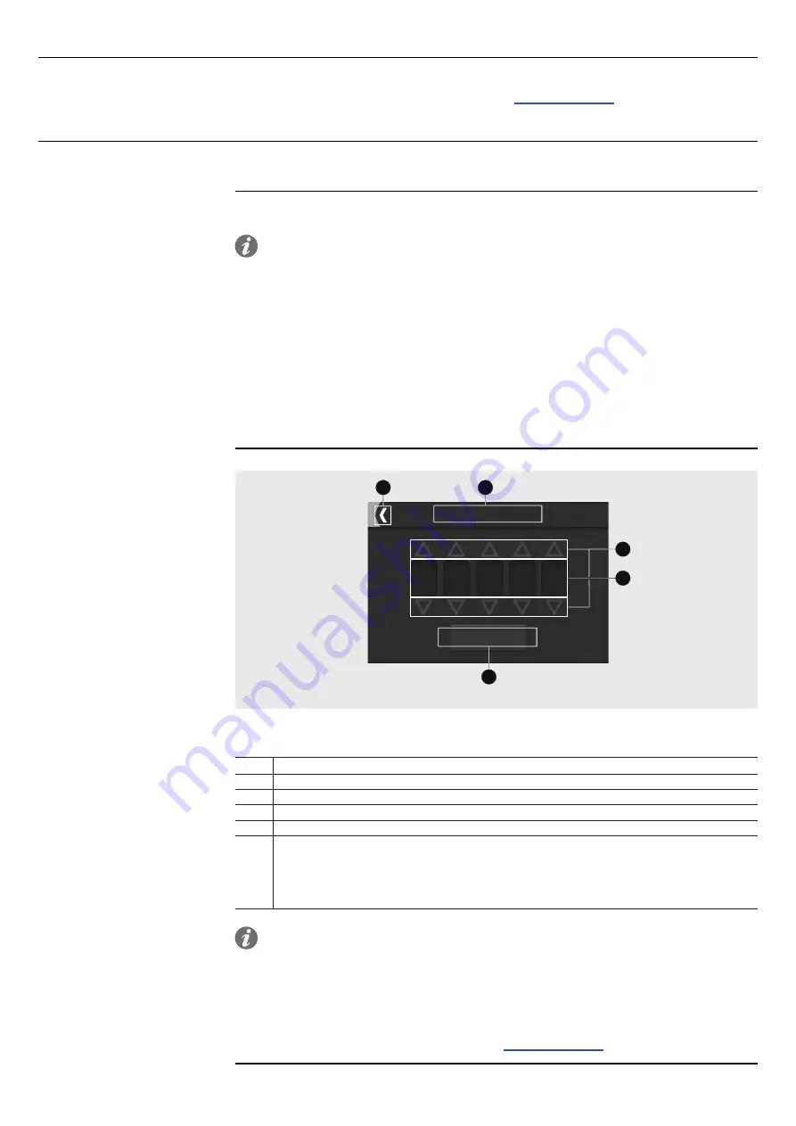
Components of the page
The page appears as follow:
C
D
*
*
*
*
0
A
B
E
Password
Confirm
Figure 5
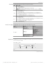
The following table provides a description of the various areas of the page:
Pos. Function
A
Cancels the operation, and opens the start menu.
B
It shows the name of the page
C
Keys to increase and decrease the corresponding digit.
D
It displays the digits of the password.
E
Confirm
key:
• Confirmation after inserting a digit in a position from 1 to 4 will automatically bring you to the
next digit.
• When the fifth digit is confirmed, the entire password is confirmed and the selected page is
opened.
NOTE:
•
If you are changing the password, after the first confirmation of the new password, the page
opens again for the reconfirmation.
•
In the case of an incorrect password, the message “Wrong Password” appears for approximately
3 seconds, and the page for insertion of the password opens again.
•
There is no limit to the number of incorrect passwords that you can insert.
•
If the password is lost, see the document


