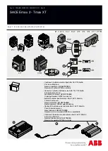
ABB | SACE Emax 2
18 | © 2017 ABB | 1SDH001330R0002 - ECN000058721 Rev. A
Ekip Dip protection trip unit | 1 - Operator interface
Ekip Dip protection trip unit
1 - Operator interface
Introduction
The operator interface of the Ekip Dip protection trip unit allows you to:
• Set the parameters relating to the available protections.
• View the status of the trip unit and alarms.
• Connect to the frontal connector to communicate and perform the opening test.
Components of the interface
The Ekip Dip operator interface appears as follows:
Figure 2
The following table provides a description of the components of the interface:
Position
Type
Description
A
LED
L Protection LED (alarm and trip)
B
L Protection LED (pre-alarm)
C
S Protection LED (alarm and trip)
D
I Protection LED (trip)
E
G Protection LED (alarm and trip)
F
Power-on LED (trip unit powered and on)
G
Protections:
thresholds
L Protection dip-switch (threshold I1)
H
S Protection dip-switch (threshold I2)
I
I Protection dip-switch (threshold I3)
L
G Protection dip-switch (threshold I4)
M
Protections: times
L Protection dip-switch (time t1)
N
S Protection dip-switch (time t2 and type of curve)
Or
G Protection dip-switch (time t4 and type of curve)
P
Settings
Neutral and frequency dip-switch
Q
Test
Test pushbutton
R
Test connector
IMPORTANT: the figure above refers to an Ekip Dip, LSIG version. In the case of Ekip
Dip LI or LSI versions, LEDs and dip-switches related only to the protections present
are available.
LEDs
The LEDs are useful on Ekip Dip in order to distinguish and identify various types of information on the
protection trip unit, the circuit-breaker and state of the line currents.
Operational conditions
The operation of the LED is determined by the power supply conditions of the trip unit:
• With the trip unit energized (by current sensors or by auxiliary power supply or by Ekip TT or by Ekip T&P
or by Ekip Bluetooth) the LEDs are operational for all the signals.
• With the trip unit de-energized, the LEDs are limited to the signalling of the last switch-off or trip event
(combined with the check via iTest, described below).
NOTE:
with the trip unit off, the operation of the LEDs is guaranteed if the internal battery of
the trip unit is working properly.
Continued on the next page
Summary of Contents for SACE Emax E1.2
Page 2: ...ABB SACE Emax 2 2 2017 ABB 1SDH001330R0002 ECN000058721 Rev A ...
Page 8: ...VI 2017 ABB SACE Emax 2 1SDH001330R0002 ECN000058721 Rev A ...
Page 9: ...ABB SACE Emax 2 3 2017 ABB 1SDH001330R0002 ECN000058721 Rev A ...
Page 310: ...ABB SACE Emax 2 304 2017 ABB 1SDH001330R0002 ECN000058721 Rev A Service 1 Power Care ...


