background image

ABB | SACE Emax 2

18 | © 2019 ABB |  1SDH001000R0002 - ECN000109166 - Rev. D

Management operations | 3 - Description

Circuit breaker racking-in/

racking-out operations

The following is the procedure for the insertion of the moving part in the fixed part:

 WARNING! 

• 

Make sure the circuit-breaker is disconnected from all sources of energy.

• 

Switch the circuit-breaker to the open position with springs discharged.


WARNING! Before proceeding, remove all equipment used during the work and remove 
processing waste and materials used.

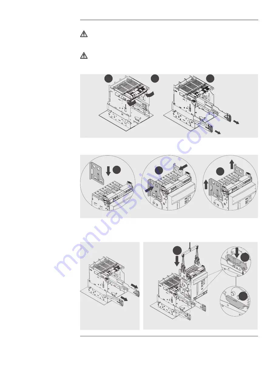
1.  Turn plate through 90° before inserting the moving part.

“CLICK”

1

2

3

Figure 1

2.  Position the lifting plates on the mobile part making sure that the tongue of the plates is latched 

properly. See Figure 37.

3

2

1

Figure 37

3.  Extract the guides of the fixed part using the appropriate levers. See Figure 38.
4.  Position the moving part on the guides of the fixed part. Latch by inserting the hollow part of the side 

in the latch of the guide of the fixed part See Figure 39.

Figure 38

1

2

3

Figure 39

Continued on the next page

Summary of Contents for SACE Emax E2.2

Page 1: ...DOC N 1SDH001000R0002 ECN000109166 Rev D SACE Emax 2 Emax low voltage air circuit breakers Emax E2 2 E4 2 E6 2 Installation operation and maintenance instructions for the installer and the user ...

Page 2: ...ABB SACE Emax 2 2 2019 ABB 1SDH001000R0002 ECN000109166 Rev D ...

Page 3: ...lation 23 Ekip Dip 31 1 General characteristics 31 2 Operating features 32 3 Operator interface 33 4 Protections 36 5 Measurements 43 6 Test 44 7 List of alarms and signals 45 8 Additional functions 47 9 Default parameters 47 Accessories 48 1 Overview 48 2 Rating Plug 49 Putting into service and maintenance 50 1 Putting into service 50 2 Identification of alarms or failures 54 3 Maintenance 58 4 F...

Page 4: ...II 2019 ABB SACE Emax 2 1SDH001000R0002 ECN000109166 Rev D ...

Page 5: ...p unit SACE Emax 2 CBs equipped with dip switch type interface Trip coil CB opening actuator controlled directly by Trip unit TRIP Concluding action of protection timing or a test command which except in special configurations applicable to the trip unit coincides with activation of the trip coil which instantly opens the bars of each pole and interrupts the circulating current Vaux Auxiliary powe...

Page 6: ...ctricity can create Trained Persons in the electrical field IEV 195 04 02 person adequately advised or supervised by electrically skilled persons to enable him or her to perceive risks and to avoid danger which electricity can create IMPORTANT This manual specifically indicates what operations can be performed by people trained in the field of electricity All the remaining operations described in ...

Page 7: ...tion instructions against certain methods of installation use and maintenance that could cause harm to personnel damage devices or make them unsafe these warnings and alarms do not include all conceivable ways to make installation use and maintenance recommended by ABB or not that may be made or possible consequences and complications of each conceivable way nor shall ABB investigate all those way...

Page 8: ...lowing international standards IEC 60947 EN 60947 CEI EN 60947 IEC 61000 UL 1066 They comply with the following EC directives Low Voltage Directives LVD no 2006 95 EC Electromagnetic Compatibility Directive EMC no 2004 108 EC The SACE Emax 2 circuit breakers also feature a range certified according to these standards Russian GOST Russia Certificate of Conformity Chinese China CCC China Compulsory ...

Page 9: ...s III IV Fs III IV Fs E2 2 46 Kg 101 lbs 58 Kg 128 lbs 53 Kg 117 lbs 60 Kg 132 lbs 41 Kg 90 lbs 49 Kg 108 lbs E4 2 63 Kg 139 lbs 77 Kg 170 lbs 67 Kg 148 lbs 81 Kg 179 lbs 57 Kg 126 lbs 69 Kg 152 lbs E6 2 118 Kg 260 lbs 134 Kg 295 lbs 151 Kg 333 lbs 129 Kg 258 lbs 143 Kg 315 lbs 159 Kg 350 lbs 96 Kg 212 lbs 109 Kg 240 lbs 123 Kg 271 lbs E2 2 A 50 Kg 110 lbs 63 Kg 139 lbs 59 Kg 130 lbs 68 Kg 150 lbs...

Page 10: ...eaker serial number 6 Features of the circuit breaker Packaging checks Examine the state of the material received and verify that The circuit breaker or the fixed part are consistent with the order The circuit breaker or the fixed part are completely intact IMPORTANT If the material is to be stored check it beforehand For opening the packaging follow the procedures outlined in the section Unpackin...

Page 11: ... storage that The circuit breaker is in the open position and the springs are discharged See the chapter Description circuit breaker opening closing operations on page 16 The circuit breaker is protected and locked in its original packaging WARNING up to three E2 2 and E4 2 circuit breaker packages and up to two E6 2 circuit breaker packages can be stacked If the packaging has been opened you can ...

Page 12: ...uit breaker safely refer to the instruction sheet in the zipped packaging pouch The following is the procedure for opening the packaging 1 Cut the bands that wrap the packing box See Figure 6 and Figure 7 Figure 6 Figure 7 2 Open the upper part of the packing box See Figure 8 3 Remove the packing box by lifting it upwards See Figure 9 Figure 8 Figure 9 Continued on the next page ...

Page 13: ...screws and the mounting brackets See Figure 11 Moving part IEC Figure 12 Moving part UL Figure 13 Fixed part IEC and Figure 14 Fixed part UL Figure 10 Fixed circuit breaker Figure 11 Moving part IEC Figure 12 Moving part UL Figure 13 Fixed part IEC Figure 14 Fixed part UL Disposal of packing materials For disposal of the packaging materials see the chapter 6 Decommissioning and treatment at end of...

Page 14: ...bs NOTE the weights indicated in the table refer to the basic circuit breakers including relays and its sensors without terminals and without accessories the weights of the withdrawable circuit breakers refer to the weight of the fixed part in a version with horizontal rear terminals Lift the fixed circuit breaker or the moving part of a withdrawable circuit breaker WARNING Improper lifting can re...

Page 15: ...ture of the poles differs between selective or current limiting circuit breaker The circuit breaker is available in two types fixed version withdrawable The circuit breaker in fixed version see Figure 18 has its own terminals for connection to the power circuit The withdrawable circuit breaker consists of a mobile part see Figure 19 and of a fixed part see Figure 20 for IEC and Figure 21 for UL fo...

Page 16: ...l signalling of tripped TU 7 Closing pushbutton 8 Springs charged discharged signalling device 9 Electrical data plate Description of electrical data plate IEC 1 9 10 4 5 11 8 7 2 3 12 6 13 Uimp 12Kv Figure 23 Pos Description 1 Type of circuit breaker 2 Utilization category 3 Device type Circuit breaker or switch disconnector 4 Rated current 5 Rated operating frequency 6 Rated voltage of accessori...

Page 17: ...l t age V 254 635 Ra t e d S hor t Cir c uit kA 100 85 S hor t Time kA Accessories AUX 4Q YO AUX 6Q YO2 RTC YC YR YC2 M YU 3A 400V AC 220V 250V AC DC 220V 250V AC DC 220V 250V AC DC 508 100 Low Vol tage AC Power Ci r cui t Br aker 63FA 85 Figure 24 Pos Description 1 Type of circuit breaker 2 Rated current 3 Rated operating frequency 4 Rated voltage of accessories 5 Rated short circuit breaking cap...

Page 18: ...rings charged signalling device B is yellow CHARGED SPRING as indicated in Figure 26 Figure 25 A B Figure 26 3 Check that the circuit breaker is open open closed signalling device O OPEN and check that the springs are charged springs signalling device yellow CHARGED SPRING as indicated in Figure 27 4 Closing Press the closing pushbutton I Push ON as indicated in Figure 28 Figure 27 Figure 28 5 Che...

Page 19: ...ready to close see Figure 35 This state occurs when after closing see step 4 Manual operations for opening and closing the circuit breaker the springs are recharged manually or automatically by the gearmotor if provided 5 Circuit breaker open with springs charged and not ready to close see Figure 36 This state occurs in the following cases The circuit breaker is open due to tripping of protection ...

Page 20: ...ding remove all equipment used during the work and remove processing waste and materials used 1 Turn plate through 90 before inserting the moving part CLICK 1 2 3 Figure 1 2 Position the lifting plates on the mobile part making sure that the tongue of the plates is latched properly See Figure 37 3 2 1 Figure 37 3 Extract the guides of the fixed part using the appropriate levers See Figure 38 4 Pos...

Page 21: ...5 Unlatch the tongue and remove the lifting plates from the moving part See Figure 40 1 2 3 Figure 40 6 Make sure that the signalling device indicates the DISCONNECT position See Figure 41 Figure 41 7 Grip the guide levers of the fixed part and push them until the moving part stops See Figure 42 Figure 42 Continued on the next page ...

Page 22: ...g part In this phase the moving part is still in DISCONNECT position See Figure 44 Figure 43 2 1 Figure 44 10 Turn the crank clockwise until the pushbutton comes out and the indicator shows that the circuit breaker is in TEST position See Figure 45 Figure 45 11 Press the lock button and rotate the crank clockwise until it comes out and the indicator shows that the circuit breaker is in CONNECT pos...

Page 23: ...d in order to be able to reach the test position Discharge the springs before removing the circuit breaker from the fixed part On the UL version the fail safe prevents the removal of the circuit breaker from the fixed part with springs charged For further details consult the Mechanical safety accessories chapter in document 1SDH001330R1002 To extract the moving part from the fixed part perform the...

Page 24: ...ing part make sure that both guides on the fixed part travel to the same extent thereby keeping the moving part parallel to the fixed part See Figure 50 Mechanical position indicators The following are the possible positions where you can find the mobile part of a withdrawable circuit breaker during its use circuit breaker in DISCONNECT position see Figure 51 circuit breaker in test position see F...

Page 25: ...breaker to the open position with springs discharged NOTE The trained personnel in charge of handling and lifting must use appropriate safety equipment Mounting of the fixed circuit breaker Fix the circuit breaker to a horizontal surface using 4 x M10 screws See Figure 54 Figure 54 WARNING Emax E2 2 E4 2 E6 2 circuit breakers can only be installed in vertical position Mounting anti insertion locks...

Page 26: ...4 2 E6 2 circuit breakers can only be installed in vertical position Lateral fixing only for circuit breakers to IEC 60068 2 6 Test Fc standards Further details about lateral fixing of fixed parts are available at http www abb com abblibrary DownloadCenter especially in the kit sheet 1SDH001000R0821 Types of terminal SACE Emax 2 circuit breakers can be equipped with different combinations of termi...

Page 27: ...Horizontal rear UL Listed Figure 63 VR Vertical rear UL Listed Figure 64 FL Flat IEC Terminal compatibility The table of terminals available for each circuit breaker is given below F HR VR SHR SVR FL E2 2 IEC 690V F W X X X X X 800V 900V X X X 1000 1150V X UL 600V X X E4 2 IEC 690V X X X 800V 900V X X X 1000 1150V X UL 600V X X E6 2 IEC 690V X X X 800V 900V X 1000 1150V X UL 600V X X ...

Page 28: ...g drawing is also available in dxf format 1SDH001301R0001 Cubicle E1 2 E2 2 E4 2 E6 2 Phase separators Phase separators are available on request Alternatively it is possible to position the insulation barriers to segregate live parts In addition the phase separators are mandatory If between two phases the minimum distance between the screws that fix the circuit breaker terminals to the connection ...

Page 29: ... 6 100x10 1 values for spread terminals circuit breaker UL 1066 Iu A Horizontal terminals Vertical terminals Q ty Dimension of busbars in Q ty Dimension of busbars in E2 2 A 1600 3 1 4 x 2 5 2 1 4 x 3 4 1 4 x 2 3 1 4 x 2 2000 4 1 4 x 2 5 4 1 4 x 2 E4 2 A 2000 4 1 4 x 2 5 4 1 4 x 2 2500 4 1 4 x 4 3 1 4 x 4 3200 4 1 4 x 4 5 1 4 x 3 E6 2 A 4000 6 1 4 x 4 4 1 4 x 5 5000 10 1 4 x 4 6 1 4 x 5 IMPORTANT ...

Page 30: ...060R0100 E6 2 III IV Fixed HR IEC 1SDH001060R0101 E6 2 III IV Fixed VR IEC 1SDH001060R0102 E6 2 IV FS Fixed HR VR IEC 1SDH001060R0104 E6 2 III IV Fixed F IEC 1SDH001060R0105 E6 2 III IV Withdrawable HR IEC 1SDH001060R0106 E6 2 III IV Withdrawable VR IEC 1SDH001060R0107 E6 2 IV FS Withdrawable HR VR IEC 1SDH001060R0108 E6 2 III IV Withdrawable F IEC 1SDH001060R0110 E6 2 6300 III IV Withdrawable FL ...

Page 31: ...type and the peak current 100 3 94 150 5 91 200 7 87 250 9 84 300 11 81 350 13 78 400 15 75 450 17 72 500 19 69 40 60 80 100 120 140 160 180 200 220 240 260 280 300 E2 2 E4 2 E6 2 L mm 1 Ipk kA 2 Figure 71 L L 1 distance of the first anchor plate from the circuit breaker terminals 2 peak current Positioning anchor plates E4 2 A 3600A The anchor plates for E4 2 A 3600A circuit breakers must be posi...

Page 32: ...he assembly is available on the website http www abb com abblibrary DownloadCenter in particular in the kit sheet 1SDH001000R0746 for fixed circuit breakers and in the kit sheet 1SDH001000R0747 for withdrawable circuit breakers Grounding The circuit breakers in fixed version and the fixed part of withdrawable circuit breakers are equipped with a screw for the ground connection The connection must ...

Page 33: ...lation currents Protection depending on the measurements made and the parameters configured by the user the Trip unit checks for the presence of alarms and commands circuit breaker opening if necessary Signalling managementofcontactsandcommunicationnetworkstooptimizeplantefficiency communication among different CB and other functions The Ekip Dip functions are provided both by means of transducers...

Page 34: ...0 A to 6300 A Self supply The internal current sensors are able to supply the Trip unit directly Parameter Operating limits Minimum three phase turn on current 30 A E2 2 with Rating Plug 400 A 80 A E2 2 with Rating Plug 400 A and E4 2 160 A E6 2 Auxiliary power supply Ekip Dip can be connected to an external auxiliary supply source which is useful when certain functions such as communication via L...

Page 35: ...ection LED alarm and trip B L Protection LED pre alarm C S Protection LED alarm and trip D I Protection LED trip E G Protection LED alarm and trip F Power on LED trip unit powered and on G Protections thresholds L Protection dip switch threshold I1 H S Protection dip switch threshold I2 I I Protection dip switch threshold I3 L G Protection dip switch threshold I4 M Protections times L Protection d...

Page 36: ...status of the protection trip unit LED on default configuration fixed or blinking signals trip unit energized LED off signals trip unit de energized NOTE with Ekip T P and Ekip Bluetooth modules and Ekip Connect software it is possible to configure how the power LED functions LED fixed or blinking Protections thresholds The thresholds of all the protections can be modified with various dip switche...

Page 37: ...tripping event NOTE with the trip unit off pressing of the iTest button switches on for approximately 4 seconds the power on LED if the trip unit is off due to an energy drop primary current less than the minimum level of operation removal of auxiliary power supply with circuit breaker open etc the protection tripped LED if the trip unit is off due to a protection trip Test connector The test conn...

Page 38: ...it When the activation threshold is exceeded the protection trips in a time that decreases as the current read increases Parameters All the parameters that can be modified by the user affect the response curve and related tripping times Parameter Description Threshold I1 The value I1 contributes in calculating the tripping time and also defines the current value that if exceeded activates the prot...

Page 39: ...I2 It defines the current value that activates the protection when exceeded with reference to the curve it is the part parallel to the y axis IMPORTANT The I2 threshold set must be higher than the I1 threshold An incorrect configuration returns an alarm signal The delay is interrupted if the current drops below the activation threshold Time t2 The selected function determines the contribution of t...

Page 40: ...djustable time Parameters The user can set the intervention threshold Parameter Description Enable By setting the threshold dip switches to the Off position the protection is disabled Threshold I3 It defines the current value that activates the protection when exceeded with reference to the curve it is the part parallel to the y axis IMPORTANT The I3 threshold set must be higher than the I2 thresh...

Page 41: ...selection NOTE calculation of the tripping time of the inverse time curve is based on a mathematical expression The details are provided in the table on page 42 Threshold I4 It defines the current value that activates the protection when exceeded with reference to the curve it is the part parallel to the y axis IMPORTANT The delay is interrupted if the current drops below the tripping threshold Fo...

Page 42: ...e protection thresholds Parameter Description Enable By setting the threshold dip switches to the Off position the protection on the Neutral is disabled Threshold InN It establishes the multiplication factor applied to the trip thresholds of the protections 50 trip threshold of the neutral current lower than other phases 100 same trip thresholds for all poles 200 trip threshold of the neutral curr...

Page 43: ...purpose of the pre alarm available for L and G protections is to signal that the measured current is near the activation threshold of the protection itself It is possible to set the pre alarm threshold in order to establish the pre alarm activation values the pre alarm threshold is expressed as a percentage in relation to the protection thresholds I1 and I4 and is adjustable between 50 and 90 defa...

Page 44: ...15 Iinst Defined by ABB Instantaneous 1 See the serigraph for the available combinations 2 t t calculation is valid for If values that have exceeded the trip threshold of the protection Use fault current and threshold values expressed in In to calculate t t as shown in the example 3 Tolerances valid with trip unit energized in service conditions or with the auxiliary tripping time 100 ms temperatu...

Page 45: ...ia the Ekip T P and Ekip Bluetooth modules and via Ekip Connect software instantaneous measurements are also available via the Ekip Multimeter unit Instantaneous currents The instantaneous currents available in the Measurements pages are real time measurements of the phase and earth fault currents expressed in root mean square value the measurement time and performance depend on the rated current ...

Page 46: ...he normal procedure Protection test In order to perform the protection test follow the instructions below Phase Operation 1 Make sure that the circuit breaker is closed and that there are no primary currents 2 Connect Ekip T P or Ekip Bluetooth to the front test connector 3 Start the communication with Ekip Connect 4 Open the Information page and select the Test command which opens the protection ...

Page 47: ...All R G All R R single G All R G All R R single G All R G G G Internal configuration error 5 x x x A Trip coil disconnected or trip command failed x B Current sensors disconnected x B Rating Plug error X B E Protection delay x C Temperature alarm 1 x C Pre alarm L x C Trip 2 x C Hardware Trip 3 x x B Installation error x E Parameter error x D Circuit breaker state not defined or in error x B Error...

Page 48: ... trip unit and accessories Rating Plug trip coil sensors etc C Normal operation signalling provided by the trip unit D Error in setting of the dip switches Check and correct the following conditions All the dip switches of L are in the ON position I1 I2 or I2 I3 Iu 2 In I1 in the case where InN 200 I4 0 3 In con In 100 A 0 25 In con In 400 A or 0 2 In for all other sizes in the absence of auxiliar...

Page 49: ...ssociate with the Ekip Signalling 10K contacts Programmable Functions Commands which activate according to the state of signals or events programmable by the user Led Alive Configuration of the Power led of the Trip unit and of all modules connected Details of these and other parameters are given in manual 1SDH001330R1002 9 Default parameters Ekip Dip default parameters The Ekip Dip trip units are...

Page 50: ...al box Communication between Trip units via an intranet with ABB proprietary protocol Other external modules and accessories Name Function Ekip Signalling 10K Programmable digital inputs outputs Ekip Multimeter Panel front display External neutral Sensor for protecting the external neutral line with 3P circuit breaker In addition the supervision configuration and reporting functions are provided b...

Page 51: ... IP54 R R Interlocks MI 5 R R S Standard R on request 1 For withdrawable version only 2 Incompatible with FAIL SAFE Can be ordered for UL on request 3 Incompatible with YU standard for UL version 4 A maximum of two accessories are available for YO and YU 5 Not available for withdrawable circuit breakers with lateral fastening 6 Incompatible with YR 2 Rating Plug Description The Rating Plug supplie...

Page 52: ...oss section 3 Correct ground connections 4 Maximum distances of separators respected Operations Perform some opening and closing operations See chapter Description of the product circuit breaker opening closing operations on page 16 The spring loading lever must move with regularly WARNING in the presence of an undervoltage coil the circuit breaker can be closed only after the trip unit is energiz...

Page 53: ...ult The circuit breaker closes correctly the signals are normal 2 Turn off the voltage supply to the trip unit The circuit breaker opens 3 Power the undervoltage coil at the relevant rated voltage and perform the closing operation on the circuit breaker Result The circuit breaker closes the signal switches over WARNING If the undervoltage coil has been tripped by a power failure the circuit breake...

Page 54: ...d stacked 1 Perform operating tests Result the interlocks function correctly Racking in out device 1 Perform a few racking in and racking out operations Result in the rack in operation the circuit breaker is connected correctly There is no particular resistance during the first turns of the handle Auxiliary accessories and auxiliary voltage Verify the proper installation The supply voltage of the ...

Page 55: ...rocedures and checked the accessories Print this sheet and use it to make an inspection report in the Checks column Operation Description Check 1 Circuit breaker OFF Open the circuit breaker 2 Circuit breaker connected Switch the circuit breaker in withdrawable version to the connected position and reposition the crank in its seat 3 Trip unit Parameters Adjust the protection trip unit in accordanc...

Page 56: ...rs IEV 195 04 01 person with sufficient training and experience to enable him or her to perceive risks and to avoid the dangers potentially created by electricity This is because it may be necessary to perform insulation and dielectric tests on part or all of the installation Some failures involve partial operation of the circuit breaker Consult the paragraphs Faults causes and remedies where the ...

Page 57: ...n reset Press the TU Reset button The power supply voltage of the auxiliary circuits is too low Measure the voltage it should not be lower than 70 of the rated voltage of the coil The power supply voltage is different from that indicated on the rating plate Check the voltage on the rating plate The cables of the coil are not inserted correctly in the terminals Make sure there is continuity between...

Page 58: ... in the terminals Make sure there is continuity between cable and terminal and if necessary reconnect the cables of the gearmotor to the terminals The connections of the power supply circuit are wrong Check the connections using the relevant wiring diagram The circuit breaker is in disconnected position Switch the circuit breaker to the test or connected position The gearmotor protection internal ...

Page 59: ...he neutral selection Zone Selectivity enabled Disable it if it is not necessary Tripping times longer than expected Threshold too high Modify the threshold Curve too high Modify the curve Wrong curve selected Modify the curve type Incorrect neutral selection Modify the neutral selection Rapid trip with I3 Off linst trip Correct operating condition with short circuit at high current High ground fau...

Page 60: ...t be carried out by Skilled Personnel electrically skilled person IEV 195 04 01 person with relevant education and experience to enable him or her to perceive risks and to avoid hazards which electricity can create ABB declines all liability for damage to persons or property caused by failure to comply with the instructions in this document Circuit breaker life The circuit breakers SACE Emax 2 wit...

Page 61: ...enance in dusty environments dust level measured 1mg m3 First Level One year or 20 of mechanical life or 20 of electrical life 6 months or 10 of mechanical life or 10 of electrical life Second Level Three years or 50 of mechanical life or 50 of electrical life or after a trip due to short circuit 18 months or 25 of mechanical life or 25 of electrical life or after a trip due to short circuit 1 Onl...

Page 62: ...detergent if necessary If there is a thick build up of dirt use a thinner from the greasing kit or ask for assistance from the service staff 2 Check that the rating plates with the technical specifications of the apparatus are present 3 Clean the rating plates with clean dry rags 4 Make sure that there are no foreign bodies in the circuit breaker compartment Circuit breaker connections and connect...

Page 63: ... screws B 2 Remove the front cover of the circuit breaker C by removing the mounting screws D A D B C 2 1 90 1 2 Figure 77 Removing the flange and front cover 3 Remove the gearmotor E by removing the screw F and the connector E E F Figure 78 Removing the gearmotor 4 If there is an undervoltage coil G remove it and discharge the springs of the operating mechanism for closing and opening the circuit...

Page 64: ...ing charging operations or reached 50 of the declared mechanical life of the circuit breaker Inspection of the protection trip unit Check that the trip unit is in good condition 1 Power the protection trip unit with an Ekip TT battery unit 2 Check the correct operation of the protection trip unit tripping test with Trip Test and Autotest 3 With a Ekip Dip verify the absence of alarms through front...

Page 65: ...perate correctly accessories if provided gearmotor if provided undervoltage coil if provided opening coil if provided closing coil if provided auxiliary contacts of the circuit breaker if provided lock for circuit breaker in open position key or padlock if provided Interlock check Check that the vertical or horizontal interlocking devices if provided are installed and that they operate correctly W...

Page 66: ...ply side and load side Inspections and general cleaning Perform the following checks 1 Make sure that the circuit breaker is clean Remove dust and oily substances or excess grease with a clean dry cloth use a mild detergent if necessary If there is a thick build up of dirt use a thinner from the greasing kit or ask for assistance from the service staff 2 Check that the rating plates with the techn...

Page 67: ... dirt use a thinner from the greasing kit or ask for assistance from the service staff 2 Make sure there there are no traces of overheating on the terminals Overheating is detected by a different coloration of the parts in contact the contact parts are usually silvery white in colour 3 Make sure that the bolts of the terminal connections are well tightened WARNING if work must be performed on fixe...

Page 68: ...g the mounting screws D C 2 1 90 1 2 Figure 83 Removing the flange and front cover 3 Remove one or both of the side guards I if installed by removing the front screws L 4 Remove the gearmotor E by removing the screw F and the connector I L Figure 84 Removing the flange E E F Figure 85 Removing the gearmotor 5 If there is an undervoltage coil G remove it and discharge the springs of the operating m...

Page 69: ...he circuit breaker e by removing the screws f and the protection plate g by removing the screw h E F Figure 87 Removing the front cover G H Figure 88 Removing the protection plate Before cleaning and lubrication of the operating mechanism you must remove the protection trip unit For information about removal see the document 1SDH001000R0523 or request the intervention of a technician ABB ...

Page 70: ...f there is a thick build up of dirt use a thinner from the greasing kit or ask for assistance from the service staff 2 Lubricate closing hook the closing shaft opening hook and opening shaft in the points indicated by the illustrations with Mobilgrease 28 grease EXXON MOBIL 3 Make sure that the opening and closing shafts are free to turn Figure 89 Lubricating the shaft and closing hook Figure 90 L...

Page 71: ...cessories are securely fixed to the circuit breaker 2 Check that the accessories are connected correctly to the circuit breaker 3 Make sure that the coils YU YO YC are in good condition no excessive wear and tear overheating rupture 4 Make sure that the mechanical operation counter functions correctly if present by operating the circuit breaker 5 Check the wear on the brushes of the gearmotor and ...

Page 72: ...f all traces of fumes and slags with a brush 4 Make sure that the contacts are in good condition 5 Visually check to make sure that the main and arc breaking plates are in place 6 Check for tarnishing or beading If such defects are discovered ask for assistance from a qualified ABB Technician 7 Check the arc breaking gaps distance A A E2 2 E4 2 E6 2 1 mm OK 4 Figure 94 Checking the breaking gaps 8...

Page 73: ...Identification of alarms or failures on page 54 4 In the absence of alarms you can proceed to the trip test and self test depending on the type of trip unit For future checks it is recommended to insert the current date in the area called Information These data will be stored within the trip unit itself 5 Remove the Ekip Bluetooth or Ekip T P unit from the trip unit Final checks Reassemble and che...

Page 74: ...nected positions Perform maintenance periodically as indicated in the table below Activity Frequency Maintenance operations Functionality 1 year or 20 of mechanical life or 20 of electrical life See kit sheet Check tightness Lubrication As shown in the figure Cables Three years or 50 of the mechanical life or 50 of the electrical life of the largest circuit breaker involved in the interlock After ...

Page 75: ...ical field IEV 195 04 02 person adequately advised or supervised by electrically skilled persons to enable him or her to perceive risks and to avoid danger which electricity can create End of life treatment for circuit breaker materials The materials used in the production of SACE Emax 2 circuit breakers are recyclable and should be treated separately as shown in the following table TYPE MATERIAL ...

Page 76: ...ABB SACE Emax 2 74 2019 ABB 1SDH001000R0002 ECN000109166 Rev D Putting into service and maintenance 6 Decommissioning and treatment at end of life ...

Page 77: ...1SDH001000R0002 ECN000109166 Rev D ...

Reviews: