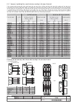
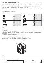
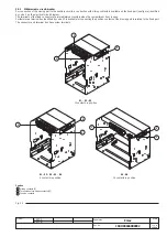
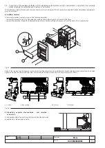
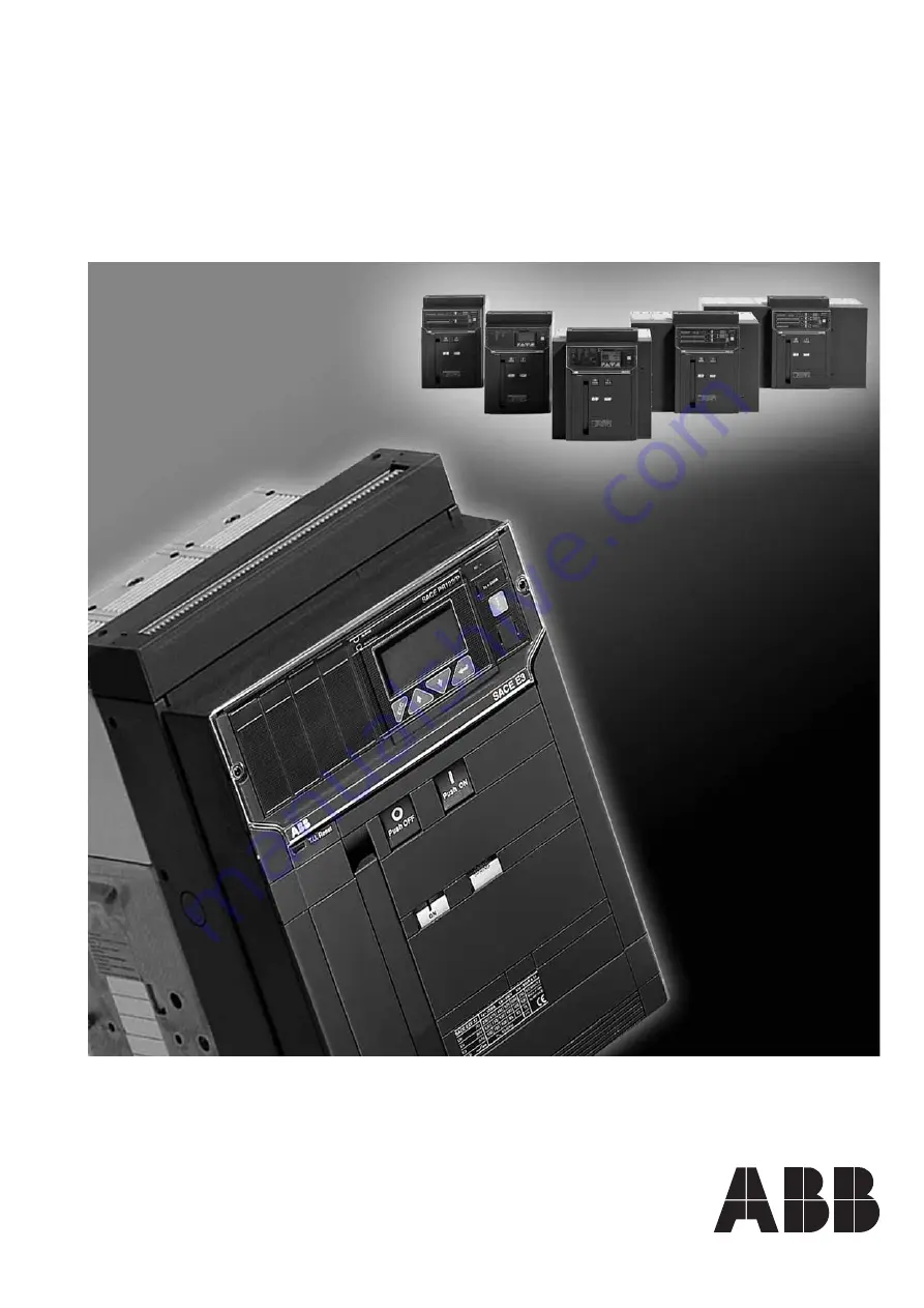
background image

Emax

Installation, service and
maintenance instructions
for low voltage air circuit-breakers

Installation and service
instructions

1SDH000460R0002      L2778

Summary of Contents for SACE Emax Series

Page 1: ...Emax Installation service and maintenance instructions for low voltage air circuit breakers Installation and service instructions 1SDH000460R0002 L2778 ...

Page 2: ...otes 29 11 1 Safety notes 30 11 1 1 Notes for dielectric stiffness tests 30 11 2 Abbreviations and notes page 30 11 2 1 Abbreviations 30 11 2 2 Notes 30 12 SACE PR121 P Release Identification 31 12 1 Standard 31 12 2 Specifications 31 12 2 1 General 31 12 2 2 Electrical characteristics 31 12 2 2 1 Self supply 31 12 2 2 2 Auxiliary power supply 31 12 2 3 Environmental characteristics 32 12 2 4 Comm...

Page 3: ...n RP 56 13 3 Putting into service 57 13 3 1 Connections 57 13 3 1 1 Current sensor connection for external neutral 57 13 3 2 VT connections 57 13 3 3 CS and TC connection test 57 13 3 4 Test 57 13 3 5 Initial settings 58 13 3 6 Password management 58 13 3 7 Replacing an electronic release page 58 13 3 7 1 Installation 58 13 3 7 2 Uninstalling 58 13 4 User interface 59 13 4 1 Use of pushbuttons 59 ...

Page 4: ... Connection 120 15 2 6 Communication functions available 120 15 2 7 PR120 D M COM module menu 120 14 2 9 1 1 Thermal memory L page 79 14 2 9 2 Protection S 79 14 2 9 2 1 Thermal memory S 79 14 2 9 2 2 Start up threshold S 79 14 2 9 2 3 Zone selectivity S 80 14 2 9 3 Double S 80 14 2 9 4 Directional Protection D 80 14 2 9 4 1 Start up threshold D 81 14 2 9 4 2 D directional zone selectivity 81 14 2...

Page 5: ...tbus 127 16 4 Data Logger recorder 128 16 4 1 General characteristics 128 16 4 2 Description of the Data Logger menu 128 16 4 2 1 Enabling the Data Logger 128 16 4 2 2 Setting the sampling frequency 128 16 4 2 3 Setting the standard stop events triggers 128 16 4 2 4 Setting and viewing customized stop events triggers 129 16 4 2 5 Setting the stopping delay 129 16 4 2 6 Restart Stop Data Logger 129...

Page 6: ...L2234 L2778 Emax 5 158 Doc No Model Apparatus Scale Page No 1SDH000460R0002 ...

Page 7: ...The structure of the poles differs according to whether the circuit breaker is selective or current limiting The fixed version circuit breaker has its own terminals for connection to the power circuit in the withdrawable version the circuit breaker comprises the moving part of the apparatus which is completed with a fixed part fitted with the terminals for connection to the power circuit of the in...

Page 8: ...ing put into service after checking it on receipt it must be put back in its container and covered with a waterproof sheet Caution Use a dry dust free room free of aggressive chemical agents as a storage room Position the circuit breaker and any fixed part on a horizontal surface not in direct contact with the floor but on a suitable support surface Fig 5 The maximum number of stackable circuit br...

Page 9: ...allation room Install the circuit breaker in a dry dust free non corrosive room and in such a way that it is not subject to shocks or vibrations Where this is not possible install it inside a switchboard with a suitable degree of protection For the preparation of the installation room please refer to the Overall dimensions paragraph whichgivesinformationonthefollowingpoints minimum installation vo...

Page 10: ...nd nuts 3 M8 x 16 supplied by ABB SACE if other screws are used make sure that the head of the screws does not extend more than 5 5 mm from the base of the fixed part 4 3 3 Installation of the fixed part on board a ship Fig 11 Regarding the fixing points of the SACE Emax withdrawable version air circuit breakers for applications on board a ship additional fixing on the sides of the fixed part itse...

Page 11: ...13 Make the compartment door drillings specified in the Overall dimensions paragraph Attach the flange 1 on the front of the compartment door fixing it from the inside by means of the self tapping screws 2 Fig 13 Fixed circuit breaker Note The drawings are provided to show the type of terminal in graphic form The exact shape of the terminals is given in the Overall dimensions chapter Different ter...

Page 12: ...5 C 55 C 35 C 45 C 55 C E1B N 08 800 800 800 800 1x 60x10 800 800 800 1x 60x10 E1B N 10 1000 1000 1000 1000 1x 80x10 1000 1000 1000 2x 60x8 E1B N 12 1250 1250 1250 1250 1x 80x10 1250 1250 1200 2x 60x8 E1B N 16 1600 1600 1600 1500 2x 60x10 1550 1450 1350 2x 60x10 E2S 08 800 800 800 800 1x 60x10 800 800 800 1x 60x10 E2N S 10 1000 1000 1000 1000 1x 60x10 1000 1000 1000 1x 60x10 E2N S 12 1250 1250 125...

Page 13: ...ween them to spread the tightening pressure over a greater area Make the contact between connection and terminal and tighten the fixing screws completely Always use two wrenches so as not to strain the insulating parts excessively applying the tightening torque indicated in Fig 18 Check tightness after 24 hours Fig 18 5 2 Earthing The fixed circuit breaker and the fixed part of the withdrawable ci...

Page 14: ...l circuit diagram The terminals of the fixed connector are immediately accessible when the compartment door is open Furthermore a terminal box identified by code XF is available for connecting the position contacts of the moving part in relation to the fixed part The connector and terminal box have screw terminals E1 E2 E3 E4 E6 5 contacts in position E4 E6 10 contacts in position E1 E2 E3 10 cont...

Page 15: ...ations remove the front protection 3 of the release by taking action on the blocks 1 as shown in the figure remove the protection release 4 removing the side nuts 2 and then sliding the release out from the front of the circuit breaker Fig 21 Being of the two way type changeover contacts the auxiliary contacts can be modified from break contacts to make contacts and vice versa simply by moving the...

Page 16: ...ase at the corresponding rated voltage if any Supply the undervoltage release at the corresponding rated voltage and carry out the circuit breaker closing operation Disconnect voltage to the release Supply the undervoltage release at the corresponding rated voltage and carry out the circuit breaker closing operation Close the circuit breaker Supply the shunt opening release at the corresponding ra...

Page 17: ... the manual opening operation 2 Lever for manual loading of the closing springs 3 Mechanical indicator for circuit breaker open O and closed I 4 Mechanical indicator for protection release tripped on request 5 Pushbutton for the manual closing operation 6 Signalling device for springs loaded unloaded 7 Operation counter on request 8 Key lock on the closing operation 9 Mechanical indicator for circ...

Page 18: ... starts reloading the springs again when the power returns It is in any case always possible to complete the reloading operation manually Fig 26 Press Fig 27 Press d Opening the circuit breaker For manual opening of the circuit breaker press pushbutton O 1 When there is a shunt opening release the operation can also be carried out remotely by means of the special control circuit Opening having tak...

Page 19: ...ng in operation to avoid any unnecessary stress C Before the racking in operation remove any padlock on the segregation shutter of the isolation terminals on the fixed part Fig 28 Press NOTES In relation to the fixed part the circuit breaker moving part can take up different positions identified as follows DISCONNECTED the moving part is inserted in the fixed part WITHOUT any connection between th...

Page 20: ...is necessary to complete the following procedure open the circuit breaker and check that the operating mechanism springs are unloaded in the case of withdrawable circuit breakers work with the circuit breaker racked out of the fixed part for action on fixed version circuit breakers or on fixed parts of withdrawable circuit breakers disconnect the supply to the power circuit and to the auxiliary ci...

Page 21: ...ar 8 3 4 Oneyearor10000operations Sixmonthsor10000operations Checkingtripoftherelease Oneyear Sixmonths Withregularordinarymaintenance With regular maintenance SACE Emax circuit breakers either with or without a geared motor can withstand the following operation without replacement of parts Rated uninterrupted current Mechanical life Electrical life Iu 40 C No of operations Frequency 440 V 690 V F...

Page 22: ...ts Problem found Presenceofdustontheinternalparts Springsdeformedorrusty Safetyringsoutofplace nutsorscrewsloose Wiresandstrapsdetached Tracesofwear Incorrectadjustments distanceA Fig 33islessthan 1 mm forE1 E2 E3orlessthan0 8mmforE4 E6 Presenceoffumesordust Presenceofcracksintheexternalplasticstructure Excessivedifferenceinwearbetweenthefirstandlast arcextinguishingplate Presenceofdustordirtonthe...

Page 23: ...ph 8 3 2 Lubricate the bearings of the drive shaft with MU EP1 AGIP grease including those on the sides of the circuit breaker Equivalent greases ESSO Beacon EP1 BP LTX1 SHELL AVANIA GREASE R1 KLUBER LUBRIFICATION CENTO PLEX 2P Lubricate the small opening and closing shafts and the hooks with 5 RX MOLY OLEOTECNICA grease Fig 33c Equivalent grease KLUBER LUBRIFICATION GRAFLOSCON A G 1 ULTRA Fig 33a...

Page 24: ...sible causes ConnectorXOnotinsertedcorrectly CoiloftheopeningreleaseYO1interrupted Defect in the electronic circuits of the microprocessor release The possible causes of tripping are listed in the part of the manualrelatingtothereleases Protectionsnotreset Operatingmechanismorconsentcontactsblockedinclosing position Auxiliarycircuitpowersupplyvoltagetoolow Differentpowersupplyvoltagefromtheoneindi...

Page 25: ...ngrelease Reference figures in the electrical circuit diagrams YO 4 YC 2 YO2 8 Undervoltage release YU The undervoltage release opens the circuit breaker in the case of a considerable drop or lack of its power supply voltage It can be used for remote tripping by means of normally closed type pushbuttons as a lock on closing or to control the voltage in the primary and secondary circuits The releas...

Page 26: ...es a delay in the tripping of the release with preset adjustable times The use of the delayed undervoltage release is recommended when the power supply network of the release can be subject to power cuts or short lived voltage drops in order to avoid trips When it is not supplied circuit breaker closing is prevented The time delay device has to be combined with an undervoltage release with the sam...

Page 27: ...d 10 2 break make contacts for PR122 PR123 5 normally open 5 normally closed 2 for the release 15 supplementary break make contacts which can be mounted outside the circuit breaker The basic configuration described above can be modified by the user to indicate normally open or normally closed by repositioning the faston connector on the microswitch When 10 contacts for PR122 PR123 are required zon...

Page 28: ...k in the connected test isolated disconnected position this allows locking only in the disconnected or test isolated positions Only available for circuit breakers in withdrawable versions for installing on the moving part e Accessories for shutter padlocks They enable the shutters to be padlocked installed on the fixed part in the closed position Only available for circuit breakers in withdrawable...

Page 29: ... three can The two half busbars can be supplied be closed at the same time by a single transformer bus tie closed or simultaneously by both bus tie open D THREE a unit of 3 supplies a single only one of the three circuit breakers can closed circuit breaker Three supplies be closed generators or transformers on the same busbar for which parallel operation is not allowed 10 3 Spare parts and retrofi...

Page 30: ...r PC with PR120 D BT or BT030 6 Freely available software for relay testing and maintenance 7 High performance data logger with 8 analogue signals and 64 digital signals which can be synchronized with hundreds of events situations of the user s choice 8 Relay powered even with the circuit breaker open using the busbar voltages with PR120 V 9 New residual current function Rc 10 Double protection G ...

Page 31: ...aged in transit Prior to servicing and or replacing the circuit breaker must be open Also remember to disconnect all power supplies connected 11 1 1 Notes for dielectric stiffness tests Dielectric stiffness tests on the releases inputs and outputs are not permitted 11 2 Abbreviations and notes 11 2 1 Abbreviations Abbreviations Meaning BA Opening coil BC Closing coil CB Circuit Breaker for example...

Page 32: ...ith the user by means of DIP switches The unit s protection parameters and general operating mode can be set entirely by the user 12 2 2 Electrical characteristics Rated operating frequency 50 60 Hz 10 Pass band 3000 Hz max Peak factor 6 3 max 2 In MTBF MIL HDBK 217E 15 years 45 C 12 2 2 1 Self supply The unit requires no outside power source for the protection and alarm signal functions It is sel...

Page 33: ...ated by the LED coming on as explained in par 12 7 1 Watchdog for proper opening solenoid connection TC Any anomalies are indicated by the LED coming on as explained in par 12 7 1 Watchdog for protection against Hw Trip If the sensors are disconnected or there is a Rating Plug error when activated a CB opening command is issued due to the TC being activated This function can be activated through a...

Page 34: ... a τL time has elapsed from the last overload or last trip or else trip time will be reduced depending on the overload and time elapsed PR121 P is equipped with two instruments to make up this thermal memory The first one is only effective when the release is powered it also records overloads that have not lasted long enough to trip the release the second operates even when the release is not powe...

Page 35: ...725 0 75 108 144 s 1 20 Ig 6 x In 0 775 0 8 0 825 0 85 0 875 3 I1 0 9 0 925 0 975 1 x In S I2 1 1 5 2 2 5 3 3 5 4 5 Where I I2 7 Ig 6 x In The best of the two data t k 6 7 8 8 5 9 9 5 10 x In t2 0 1 0 2 0 3 0 4 0 5 0 6 10 Ig 6 x In 10 or 40ms 0 7 0 8 s S I2 1 1 5 2 2 5 3 3 5 4 5 t2 0 1 0 2 0 3 0 4 0 5 0 6 7 Ig 6 x In 15 Ig 6 x In t k I2 6 7 8 8 5 9 9 5 10 x In 0 7 0 8 s 10 Ig 6 x In 20 Ig 6 x In 1...

Page 36: ...5 15 0 4 1 0 4 L 1 5 12 2 9 Trip curves The trip curves provided are merely for guidance and only show a sub group of the possible selections see par 12 2 7 12 2 9 1 Trip curves for functions L I 12 2 9 2 Trip curves for functions L S t k I2 I 1 5 15 0 4 1 0 4 1 5 L 0 1 0 8 t k I2 ...

Page 37: ...x 36 158 Model Scale Page No Doc No Apparatus 1SDH000460R0002 L2778 12 2 9 3 Trip curves for functions L S t k I 12 2 9 4 Trip curves for function G 0 2 1 0 2 0 1 0 8 t k t k I2 0 4 1 0 4 1 5 1 5 15 0 1 0 8 t k ...

Page 38: ...TC and or CS cables before putting the circuit breaker into service if this has not been done make the right connections If any of the red LEDs come on this means an error in the connection of the CS and or TC See par 12 7 1 12 4 3 Current sensor connection for external neutral If you want to connect the current sensor for the external neutral conductor to a three pole circuit breaker remember to ...

Page 39: ...ker opening see Watchdog To be able to do the test you need to connect the PR030 B battery unit 12 5 2 Initial settings ABB SACE will see to applying the adhesive labels on the PR121 P for all the variables relating to the circuit breaker e g Type of circuit breaker Rating Plug size etc It should be noted that ABB SACE provides a sensible definition for each possible setting see par 12 5 4 Before ...

Page 40: ...oring it to within the accepted limits With a 3 pole CB with external neutral the relay performs no checks and setting is to be done by user E g With E1B800 CB having a 400A Rating Plug Iu 800A and I1 1In In N adjustment may be 50 100 200 With E1B800 CB having a 800A Rating Plug Iu 800A and I1 1In In N adjustment may be 50 100 Note 1 I1 1ln setting is intended as the maximum adjustment of the prot...

Page 41: ...r or when Ne protection is set to ON on the 3p CB without external neutral configuration error When Vaux and or PR030 B are installed connected during the event trip cause is displayed CS Error Rating Plug Error When no Vaux and or PR030 B are installed the general Hw trip indication is retained and can be viewed by pressing the I Test key 4 Orange L led and red I led on 5 The values entered diffe...

Page 42: ...ote of which LED is on also recording the type of CB the number of poles any connected accessories the In and the serial number see par 12 5 2 Prepare a brief description of the opening what LEDs were displayed when did it happen how many times was it always under the same conditions what type of load what current is the event reproducible 3 Send communicate all the information collected together ...

Page 43: ...ection against L overload with inverse long time delay S short circuit with adjustable delay I instantaneous short circuit G earth fault with adjustable delay U phase unbalance OT temperature out of range MCR closing on short circuit The PR122 P can be installed on 3 pole CBs with and without an external neutral or on 4 pole CBs It should be noted that the reference current for the PR122 P is the ...

Page 44: ...ed in IEC 478 1 and CEI 22 3 no greater than 3 5mA The presence of the auxiliary power supply enables the relay unit to be used even with the circuit breaker open as well as powering all the modules The characteristics of the power pack are given in the table below Characteristics Version PR122 P Auxiliary voltage galvanically separated 24V DC 20 Maximum ripple 5 Inrush current 24V 10 A for 5ms Ra...

Page 45: ...wered from the optional PR120 V the PR122 P unit records the state of the circuit breaker by means of specific wiring on the circuit breaker In the case where the presence of current is determined with the circuit breaker in the OPEN state a state error is signaled by a warning message being displayed see par 13 6 and the warning LED lighting up The signal can be combined with a relay of the PR120...

Page 46: ...al memory The first is only effective when the release is powered it also records overloads that have not lasted long enough to trip the release while the second works even when the release is not powered reducing any trip times in the case of an immediate reclosing and is enabled as soon as the CB is tripped It is the PR122 P release that automatically decides which of the two to use according to...

Page 47: ... trip Excluded NO 1 0 No trip Excluded YES 0 0 t2 programmed Excluded YES 1 0 t2 programmed Inserted NO 0 0 No trip Inserted NO 1 1 No trip Inserted YES 0 1 tselectivity Inserted YES 1 1 t2 programmed The time t2 must be set at a value higher than or equal to tselectivity 50ms on the CB on the supply side not required on the first one in the chain 13 2 9 3 Protection I The protection is enabled di...

Page 48: ...2 Zone selectivity G The zone selectivity function can be enabled providing the fixed time curve is selected and function is assured only if auxiliary voltage is provided Zone selectivity G can be active at the same time as zone selectivity S The behavior and wiring of the function are identical to those indicated for zone selectivity S see par 13 2 9 2 3 13 2 9 6 Protection against phase unbalanc...

Page 49: ...r open When the circuit breaker is closed or the passage of a current is detected you pass immediately from the state of alarm to TRIP without timing see par 13 3 2 13 2 9 9 1 Protection UV When the minimum phase voltage drops below the set threshold U8 the protection counts down the preset time interval t8 and then opens 13 2 9 9 2 Protection OV When the maximum phase voltage exceeds the set thre...

Page 50: ... Ig 6 In The best of the two data t k step 0 1xIn 0 10 s t2 start up 30 s step 0 01s 10 Ig 6 In 10 or 40 ms 0 6 xIn I2 start up 10xIn 0 04 s t2 sel 0 20 s step 0 01s step 0 1xIn S 0 6xIn I2 10xIn 0 05 s t2 0 8 s 7 Ig 6 In 15 Ig 6In t k i2 step 0 1xIn step 0 01s at 10xIn 10 Ig 6 In 20 Ig 6In I 1 5xIn I3 15xIn 30ms t k step 0 1xIn 0 10 s t2 start up 30 s step 0 01s 10 where I I4 MCR 6 0xIn I5 15xIn ...

Page 51: ...e threshold 2 13 2 9 12 2 Table of measurements Type of measurement Standard operation range Range of values measured by the relay Range Tolerance Phase and neutral currents 0 05 16 In 0 3 6 In 1 5 Internal ground fault current 0 05 4 In 0 3 4 In 1 5 internal source round return External ground fault current 0 05 4 In 0 3 4 In 1 5 external source round return Phase to phase and phase voltages 10 V...

Page 52: ...up of the possible selections see par 13 2 9 11 13 2 10 1 Trip curves for functions L I t s 10 1 10 2 1 10 102 103 104 10 3 1 10 100 10 1 x In 0 4 1 0 4 1 1 5 15 0 05 0 8 1 5 15 3 144 L I t s 10 1 10 2 1 10 102 103 104 10 3 1 10 100 10 1 x In 0 4 1 1 5 15 1 5 15 0 6 10 0 6 10 0 05 0 8 0 4 1 3 144 L I S t k I 2 13 2 10 2 Trip curves for functions L S t k i2 I ...

Page 53: ...2 103 104 10 3 1 10 100 10 1 x In 0 4 1 0 4 1 1 5 15 0 6 10 0 6 10 0 05 0 8 1 5 15 3 144 L I S t k 13 2 10 3 Trip curves for functions L S t k I 13 2 10 4 Trip curves for function L in accordance with IEC 60255 3 type A t s 10 1 1 10 102 103 104 10 1 1 10 100 x In 3 144 0 4 1 0 4 1 L k 0 14 0 02 a α ...

Page 54: ...p curves for function L in accordance with IEC 60255 3 type B 13 4 2 10 6 Trip curves for function L in accordance with IEC 60255 3 type C t s 10 1 1 10 102 103 104 1 10 100 10 1 x In 0 4 1 1 0 4 3 144 L k 13 5 1 a α t s 10 1 1 10 102 103 104 1 10 100 10 1 x In 0 4 1 0 4 1 3 144 L k 80 2 a α ...

Page 55: ...460R0002 L2778 13 2 10 7 Trip curves for function G 1 10 100 10 1 x In t s 10 2 1 10 102 103 104 10 3 10 1 10 0 2 1 0 2 1 0 1 1 G t k G t k I 2 t s 1 10 10 1 1 10 102 103 104 10 2 x In 10 1 0 02 0 5 10 0 5 60 0 9 60 0 02 0 9 U 13 2 10 8 Trip curves for function U ...

Page 56: ...78 t s 10 1 10 2 1 10 102 103 104 0 3 0 5 0 7 0 9 1 1 1 3 x Un 0 1 0 5 0 95 0 5 0 95 10 0 1 5 5 UV 13 2 10 9 Trip curves for function UV t s 10 1 10 2 1 10 102 103 104 1 1 05 1 1 1 15 1 2 1 25 1 3 x Un 1 05 1 2 10 0 1 5 1 05 1 2 0 1 5 OV 13 2 10 10 Trip curves for function OV ...

Page 57: ...o Apparatus 1SDH000460R0002 L2778 t s 10 1 1 10 102 103 104 0 0 2 0 4 0 6 0 8 1 x Un 1 2 10 0 5 30 0 5 0 1 0 4 30 0 1 0 4 RV 13 2 10 11 Trip curves for function RV 0 3 0 1 0 3 0 3 0 5 25 0 5 0 1 0 2 0 3 0 4 13 2 10 12 Trip curves for function RP ...

Page 58: ...rs see par 15 1 7 The VTs must have a performance coming between the values of 10 and 20 VA inclusive 4 kV insulation between the primary and secondary NotefordiagramB for TN C systems the connection must be made to PEN for TN S systems the connection must be made to N for configurations with neutral or PE for configurations without neutral if the PE is used the current thereon could be around a d...

Page 59: ...ressed Disabling the Password By setting the value of the password to 0000 on the Unit configuration menu the password prompt is disabled It is therefore always possible to switch from READ to EDIT To enter a new password select the New Password item on the Settings System menu 13 3 7 Replacing an electronic release 13 3 7 1 Installation To complete the procedure for installing a PR122 P unit foll...

Page 60: ...ey To confirm the programming of the previously configured parameters press the ESC key to scroll up the menus till the programming confirmation page will be displayed select confirmation and press ENTER for data programming The i Test key must be used to perform the Trip test to view the information page and to see the last trip within 48 hours of the CB opening in self supply mode Ref Descriptio...

Page 61: ... Cancel Change any changes you have made This procedure is not applicable to all the programming activities Two examples are provided below one concerns the case in which no confirmation is needed for the changes you have made while in the other a confirmation window appears Procedure not requiring the confirmation of any programming For instance to set the System Date the correct sequence is as f...

Page 62: ...to access the Main Menu N 10 22 53 400 A I 1 Password Enter password 0 Date Enter password January 12 2004 1 5 Protections settings Measures Settings Protections Menu 1 5 Protections settings Measurements Settings Protections Menu 1 13 Overload S Protection I Protection L Protection Protections 1 4 Threshold I1 Time T1 Function L Protection t k i2 Password Enter password 0 From the Main Menu selec...

Page 63: ...unction 1 3 Confirm Abort Modify Confirm Programming 1 4 January 12 2003 Time Language Date System 4 4 Language New Password Time System Password Enter password 0 To change the system password select the relevant menu item and press enter then you will be prompted to enter the OLD password and afterwards you can input the new one twice Press ESC twice to return to the Main Menu Before accessing th...

Page 64: ... 9 U V Off 0 9Un 5s Off 10 O V Off 1 05Un 5s Off 11 R V Off 0 15Un 15s Off 12 RP Off 0 1Pn 10s Off 13 U F Off 0 9Fn 3s Off 14 O F Off 1 1Fn 3s Off 15 Language Engl 16 Net Frequency 50Hz 17 PR021 K Off 18 Neutral sel 19 Toroid Selec None 20 Ext ground tor Off 100A 21 Rated Voltage 380V 400V 690V 22 S startup Off 6In 100ms 23 I startup Off 4In 100ms 24 G startup Off 1In 100ms 25 Password 0001 26 Mea...

Page 65: ...B open Auto Test Trip Test disabled CB status Test 6 6 Device test SIGNALLING module COM module Zone selectivity Test 1 5 Protections settings Measurements Settings Protections Menu Trip measures log Power factor Energy Historicals Measurements 1 7 2 5 Measures graphics harmonics Measurements Settings Protections Menu Main Frequency Contact Wear Peak factor Measurements 6 7 0 0 3 5 General setting...

Page 66: ... Password prompt then you can select the functions associated with the protection L as in the example Example of how to select the curve t k i2 Similarly to access the menus for the other protections see the Protections Menu table below 13 5 2 1 Protections menu table Protection Parameter Function L Curve Threshold I1 Time t1 Thermal memory ON OFF S Enable ON OFF Curve Threshold I2 Time t2 Zone se...

Page 67: ...reshold I4 Time t4 Enable Trip ON OFF Zone selectivity ON OFF Selectivity time Enable StartUp ON OFF StartUp threshold StartUp time RC Threshold I4 Time t4 U Enable ON OFF Function Currents Voltages Threshold I6 Time t6 Enable Trip ON OFF UV Enable ON OFF Threshold U8 Time t8 Enable Trip ON OFF OV Enable ON OFF Threshold U9 Time t9 Enable Trip ON OFF RV Enable ON OFF Threshold U10 Time t10 Enable ...

Page 68: ...F OF Enable ON OFF Threshold f13 Time t13 Enable Trip ON OFF OT Enable Trip ON OFF Load Control Threshold 1 Enable ON OFF Threshold Threshold 2 Enable ON OFF Threshold Threshold lw Enable ON OFF Threshold Note for an explanation of the characteristics of the single protections and their settings and corresponding curves see par 13 2 9 ...

Page 69: ...ections settings Measurements Protections Menu Settings 1 8 Circuit breaker settings Main Frequency Modules Circuit Breaker Settings 2 3 Neutral settings Neutral Protection Unit installation Ground protection Circuit Breaker On Neutral threshold Enable Neutral protection 21 2 Enter Enter PWD Parameter Function Values Notes Circuit Neutral protection breaker Enable ON OFF Neutral threshold 50 100 1...

Page 70: ... Modules When you access the Settings menu there is a set of menus available relating to the modules 13 5 4 4 1 PR120 V MEASURING module In the measuring module you must enter a password and can then opt for the absence or presence of the voltage transformer Moreover you can select the values of the primary voltage 100 115 120 1000V and secondary voltage 100 110 230V The power flow can be LOW HIGH...

Page 71: ... module SIGNALLING module MEASURING module Modules 1 5 Local Serial Address Baudrate Local Remote COM module 13 5 5 Test Menu Access to the Test menu is password protected The menu shows the state of the CB in the dialog module COM module the state of the springs and the position of the CB and in this submenu you can make the CB open or close Using the Trip Test function lets you view the disablin...

Page 72: ...ute current interrupted during each of them 13 6 2 Electrical signals K51 p1 p4 Programmable electrical signals if the PR120 K module is installed and there is an auxiliary power supply K51 p1 p8 Programmable electric signals if the PR021 K unit is installed and there is an auxiliary power supply Pressing the i Test key enables resetting the activated contacts 13 6 Definition of alarms and signals...

Page 73: ...larm with no trip trip off TC disconnected Trip Coil disconnected or faulty Rating Plug Rating Plug Error absent or faulty Power factor Alarm for power factor The power factor module is lower than the specified threshold Phase cycle Phase cycle inverted Invalid date Clock information lost CB status CB state error Probable error in Q26 and or Q27 Installation Key Plug Error CB not defined Stateofci...

Page 74: ...evised Programming session concluded correctly Cancelled Programming session cancelled Failed Programming session rejected Failed 1001 Inconsistent thresholds of protections L and S Failed 1002 Inconsistent thresholds of protections I and S Failed 1009 Zone selectivity enabled in both protection S and G or Gext Failed 3001 Inconsistency as to language change Failed 3002 Inconsistency on Rc toroid ...

Page 75: ...ng and the current and or 1 FN see 13 2 2 1 voltages are below the minimum value 2 Temperature out of range 2 FN see 13 2 9 8 7 The display is not back lit Current and or volatges below the FN limit for lighting the display 8 Reading of I incorrect Current below the minimum threshold FN that can be displayed 9 Reading of V W and power factor 1 Connection error between VT and 1 Check connections be...

Page 76: ...will facilitate technical analysis of the problem encountered and will allow us to carry out all actions useful for the user rapidly 13 8 Accessories 13 8 1 ABB SACE PR010 T test and configuration unit Testing by the SACE PR010 T unit allows checking correct operation of thresholds and trip times of L S I G OV UV RV U protection functions The test unit is connected to the relay through a dedicated...

Page 77: ...voltage RP reverse active power UF underfrequency OF overfrequency MCR closing on short circuit The PR123 P can be installed on 3 pole CBs with and without an external neutral or on 4 pole CBs It should be noted that the reference current for the PR123 P is the In the rated current defined by the front Rating Plug and not the Iu the uninterrupted rated current of the CB itself Example the CB E1B80...

Page 78: ...4V DC 20 Maximum ripple 5 Inrush current 24V 10A for 5ms Rated power 24V 5W 14 2 2 3 Powered by the PR120 V module For a full explanation of the features of the PR120 V see par 15 1 14 2 3 Environmental characteristics Operating temperature 25 C 70 C Storage temperature 40 C 90 C Relative humidity 0 98 with condensation Degree of protection with PR123 P installed in the CB IP 30 14 2 4 Description...

Page 79: ...ring on the circuit breaker In the case where the presence of current is determined with the circuit breaker in the OPEN state a state error is signaled by a warning message being displayed see par 14 6 and the warning LED lighting up The signal can be combined with a relay of the PR120 K module or with those of the PR021 K unit 14 2 7 Measurement functions The current measuring ammeter function i...

Page 80: ...he trip time will be reduced depending on the overload which has occurred and on the time that has elapsed The PR123 P is fitted with two instruments to make up this thermal memory The first is only effective when the release is powered it also records overloads that have not lasted long enough to trip the release while the second works even when the release is not powered reducing any trip times ...

Page 81: ...d to be identified and isolated without interfering with the rest of the installation using zone selectivity To determine the direction of the current the value of the phase reactive powers has to be higher than 2 of the nominal phase power PQ 2 Pnphase The PR123 enables you to define the power flow in the circuit breaker from the menu from high to low Top Bottom from low to high Bottom Top select...

Page 82: ...e protection S see par 14 2 9 2 2 14 2 9 4 2 D directional zone selectivity The Directional Zone Selectivity SdZ D function is particularly useful in ring and grid type systems where in addition to the zone it is essential to define the direction of the power flow that powers the fault The SdZ D can be set as an alternative to Zone Selectivity S and G and requires an auxiliary power supply To defi...

Page 83: ...the programmed times between t7fw and t7bw without enabling any outputs DFout or DBout If for some reason one of the circuit breakers required to open does not do so a specific function will activate the opening of the first circuit breaker immediately upstream from it after a further 100ms approx In the above example if the circuit breaker does not open with the relay1 only the circuit breaker wi...

Page 84: ...y The minimum allowable threshold for the Gext protection is 0 1 x In where In is the rated current of the homopolar toroidal transformer the In settings available are 100 250 400 800A 14 2 9 7 1 Start up threshold G The start up function can be selected in the case where the curve with fixed time is selected The function can be enabled and disabled on the protection G page The function behaves in...

Page 85: ...e defined as alarm with the emergency led on and an alarm message displayed providing there is an auxiliary or PR120 V module power supply In fact in the case where the circuit breaker is open and no current is detected the timing leads to the alarm state and not to TRIP This is because the fault linked to the voltages can persist even with the circuit breaker open and the unit would therefore alw...

Page 86: ...pable of changing the load capacity and the short circuit levels The second set of parameters set B can be enabled by digital input provided with the PR120 K module For instance it can be connected to an auxiliary contact of a bus tie communication network by means of the PR120 D M e g when the switch is scheduled directly from the user interface on the PR123 P see settings menu par 14 5 4 with a ...

Page 87: ...1xIn 0 1s t4 1s step 0 05s 7 15 t k I2 step 0 02xIn Ig 4In Gext 0 20xIn I4 1xIn 0 1s t4 1s step 0 05s The best of the two data t k step 0 02xIn 0 1s t4start up 30s step 0 02s 7 10 or 40 ms 0 04s t4sel 0 2s step 0 01s Gext 0 20xIn I4 1xIn 0 1s t4 1s step 0 05s 7 15 t k I2 step 0 02xIn at Ig 4In Rc Idn 3 0 5 0 7 0 10 20 0 06 0 10 0 20 0 30 0 40 0 50 140ms 0 06s 5 Idn 30A 0 80s 3 0 20 950ms 0 80s 5 U...

Page 88: ...art up threshold Thermal memory 14 2 9 16 Table of measurements Type of measurement Standard operation range Range of values measured by the relay Range Tolerance Phase and neutral currents 0 05 16 In 0 3 6 In 1 5 Internal ground fault current 0 05 4 In 0 3 4 In 1 5 internal source round return External ground fault current 0 05 4 In 0 3 4 In 1 5 external source round return Phase to phase and pha...

Page 89: ... 0 8 0 4 1 3 144 L I S t k I 2 t s 10 1 10 2 1 10 102 103 104 10 3 1 10 100 10 1 x In 0 4 1 0 4 1 1 5 15 0 6 10 0 6 10 0 05 0 8 1 5 15 3 144 L I S t k 14 2 10 Trip curves The trip curves given are for guidance and only show a sub group of the possible selections see par 14 5 2 14 2 10 1 Trip curves for functions L S t k I2 I 14 2 10 2 Trip curves for functions L S t k I ...

Page 90: ...No Apparatus 1SDH000460R0002 L2778 14 2 10 3 Trip curves for function G 14 2 10 4 Trip curves for function L in accordance with IEC 60255 3 type A 0 1 1 0 2 1 0 2 t s 10 1 1 10 102 103 104 10 1 1 10 100 x In 3 144 0 4 1 0 4 1 L k 0 14 0 02 a α ...

Page 91: ...ip curves for function L in accordance with IEC 60255 3 type B 14 2 10 6 Trip curves for function L in accordance with IEC 60255 3 type C t s 10 1 1 10 102 103 104 1 10 100 10 1 x In 0 4 1 1 0 4 3 144 L k 13 5 1 a α t s 10 1 1 10 102 103 104 1 10 100 10 1 x In 0 4 1 0 4 1 3 144 L k 80 2 a α ...

Page 92: ... 1SDH000460R0002 L2778 t s 1 10 10 1 1 10 102 103 104 10 2 x In 10 1 0 02 0 5 10 0 5 60 0 9 60 0 02 0 9 U 14 2 10 7 Trip curves for function D 14 2 10 8 Trip curves for function U t s 1 10 100 1 10 102 103 104 10 2 x In 10 1 10 1 D 10 0 2 0 8 0 6 10 0 6 10 ...

Page 93: ...78 t s 10 1 10 2 1 10 102 103 104 0 3 0 5 0 7 0 9 1 1 1 3 x Un 0 1 0 5 0 95 0 5 0 95 10 0 1 5 5 UV t s 10 1 10 2 1 10 102 103 104 1 1 05 1 1 1 15 1 2 1 25 1 3 x Un 1 05 1 2 10 0 1 5 1 05 1 2 0 1 5 OV 14 2 10 9 Trip curves for function UV 14 2 10 10 Trip curves for function OV ...

Page 94: ...0R0002 L2778 t s 10 1 1 10 102 103 104 0 0 2 0 4 0 6 0 8 1 x Un 1 2 10 0 5 30 0 5 0 1 0 4 30 0 1 0 4 RV t s 10 1 1 10 102 103 104 0 1 x Pn 0 0 3 0 4 0 2 10 0 5 25 0 5 25 0 3 0 1 0 3 0 1 RP 14 2 10 11 Trip curves for function RV 14 2 10 12 Trip curves for function RP ...

Page 95: ...ar 15 1 7 The VTs must have a performance coming between the values of 10 and 20VA inclusive 4 kV insulation between the primary and secondary Note for B diagram for TN C systems the connection must be made to PEN for TN S systems the connection must be made to N for configurations with neutral or PE for configurations without neutral if the PE is used the current thereon could be around a dozen m...

Page 96: ...the value of the password to 0000 on the Unit configuration menu the password prompt is disabled It is therefore always possible to switch from READ to EDIT To enter a new password select the New Password item on the Settings System menu 14 3 7 Replacing an electronic release 14 3 7 1 Installation To complete the procedure for installing a PR123 P unit follow the steps below 1 With the circuit bre...

Page 97: ... page 12 TEST connector for connecting or testing the release by means of an external device PR030 B battery unit BT030 wireless communication unit and PR010 T test unit 13 i Test test and info button 1 2 3 4 5 6 7 13 12 11 10 9 8 14 4 1 Use of pushbutton The modifiable fields can be filled in using the or keys and confirming with the key Once you have entered the page you need you can move from o...

Page 98: ...gramming you need to Confirm Cancel Change any changes you have made This procedure is not applicable to all the programming activities Two examples are provided below one concerns the case in which no confirmation is needed for the changes you have made while in the other a confirmation window appears Procedure not requiring the confirmation of any programming For instance to set the System Date ...

Page 99: ...he Main Menu From the Main Menu select the item PROTECTIONS press the key enter From the Protections Menu select the item PROTECTION L press the key enter Date Enter password January 12 2004 Password Enter password 0 N 10 22 53 400 A I 1 1 5 Protections settings Measures Settings Protections Menu 1 5 Protections settings Measurements Settings Protections Menu 1 15 Overload S Protection S2 Protecti...

Page 100: ...hange the system password select the relevant menu item and press enter then you will be prompted to enter the OLD password and afterwards you can input the new one twice Press ESC twice to return to the Main Menu Before accessing the Main Menu the following box will appear Accept the new configuration Reject the new configuration the previous configuration is retained Change the previously input ...

Page 101: ... K LC2 Off 75 I1 10 UV Off 0 9 Un 5 s Off 11 OV Off 1 05 Un 5 s Off 12 RV Off 0 15 Un 15 s Off 13 RP Off 0 1 Pn 10 s Off 14 UF Off 0 9 Fn 3 s Off 15 OF Off 1 1 Fn 3 s Off 16 Language Engl 17 Net Frequency 50 Hz 18 PR021 K Off 19 Neutral sel 20 Toroid Selec None 21 Ext ground tor Off 100 A 22 Rated Voltage 380V 400V 690V 23 S startup Off 6 In 100 ms 24 I startup Off 4 In 100 ms 25 G startup Off 1 I...

Page 102: ...p Test disabled CB status Test 6 6 Device test SIGNALLING module COM module Zone selectivity Test 1 5 Protections settings Measurements Settings Protections Menu Trip measures log Power factor Energy Historicals Measurements 1 7 2 5 Measures graphics harmonics Measurements Settings Protections Menu Main Frequency Waveforms ear Peak factor Measurements 6 7 3 5 General settings Measurements Settings...

Page 103: ... select the functions associated with the protection L as in the example Example of how to select the curve t k i2 14 5 2 1 Protections Menu table Protection Parameter Function L Curve Threshold I1 Time t1 Thermal memory ON OFF S Enable ON OFF Curve Threshold I2 Time t2 Zone selectivity ON OFF Selectivity time Enter Enter Percentage of the actual currents and voltages with respect to the rated val...

Page 104: ...ld I7 Time t7 Fw Time t7 Bw Zone selectivity ON OFF Selectivity time Enable StartUp ON OFF StartUp threshold StartUp time I Enable ON OFF Threshold I3 Enable StartUp ON OFF StartUp threshold StartUp time G Enable ON OFF Curve Threshold I4 Time t4 Enable Trip ON OFF Zone selectivity ON OFF Selectivity time Enable StartUp ON OFF StartUp threshold StartUp time Gext Enable ON OFF Curve Threshold I4 Ti...

Page 105: ...ip ON OFF RV Enable ON OFF Threshold U10 Time t10 Enable Trip ON OFF RP Enable ON OFF Threshold P11 Time t11 Enable Trip ON OFF UF Enable ON OFF Threshold f12 Time t12 Enable Trip ON OFF OF Enable ON OFF Threshold f13 Time t13 Enable Trip ON OFF OT Enable Trip ON OFF Load control Threshold 1 Enable ON OFF Threshold Threshold 2 Enable ON OFF Threshold Threshold lw Enable ON OFF Threshold Note for a...

Page 106: ...eshold values 50 100 150 200 the external toroid size values 100A 250A 400A 800A the mains frequency at the installation values 50Hz 60Hz For a more detailed description of the settings for the modules refer to the documentation on the modules ch 15 1 5 Protections settings Measurements Settings Protections Menu 1 9 Circuit breaker settings Main Frequency Modules Circuit Breaker Settings 1 3 Neutr...

Page 107: ...justment The neutral protection is normally set to a current value 50 of the adjustment made on the phases In some installations where particularly high harmonics occur the current circulating on the neutral may be higher than that of the phases In the SACE PR123 P release this protection can be set for the following values In N 50 100 150 200 In 14 5 4 2 1 Neutral adjustment specifications To adj...

Page 108: ...5 4 4 4 PR120 D WL COM module This module is for wireless communication based on the Bluetooth standard between the PR123 P protection release and a hand held PC PDA or a laptop with a Bluetooth port For further information see the description of the module in paragraph 15 4 14 5 4 4 5 Settings for the Local Bus unit If the PR021 K unit is connected you need to enable the local bus by selecting pr...

Page 109: ... an auxiliary power supply the information is shown immediately on the display without the need to press the i Test key and remains displayed indefinitely until you press the key The information remains available for 48 hours with dead relay The data relating to the last 20 trips are stored in the unit s memory By connecting a PR030 B battery unit and PR010 T or a BT030 wireless communication unit...

Page 110: ...s Timing in progress for the reverse active power protection function RP Timing in the case of unbalance between the phases protection U above the value set in the configuration with protection trip set to on Contact wear 100 Rating Plug disconnected Trip Coil TC disconnected Key plug error Current sensors disconnected Installation error The IEC 60947 2 Standard defines the timing threshold L for ...

Page 111: ...xceeded Timing L Timing protection L Timing S Timing protection S Timing S2 Timing protection S2 Timing G Timing protection G Timing Gext Timing protection Gext Timing D Timing protection D Timing U Timing protection U Timing UV Timing protection UV Timing OV Timing protection OV Timing RV Timing protection RV Timing RP Timing protection RP Timing UF Timing protection UF Timing OF Timing protectio...

Page 112: ... of range 2 FN see 14 2 9 8 7 The display is not back lit Current and or voltages below the FN limit for lighting the display 8 Reading of I incorrect Current below the minimum threshold FN that can be displayed 9 Reading of V W and power 1 Connection error between VT 1 Check connections between VT and factor incorrect and PR120 V PR120 2 Voltage parameter setting error 2 Set correct parameters 10...

Page 113: ...ce will facilitate technical analysis of the problem encountered and will allow us to carry out all actions useful for the user rapidly 14 8 Accessories 14 8 1 ABB SACE PR010 T test and configuration unit The test with the SACE PR010 T unit enables to check the proper operation of thresholds and tripping times of the protection functions L S I G OV UV RV U The test unit is connected to the relay b...

Page 114: ...test position Dielectric strength tests on the secondary lines of Voltage Transformers connected if any are not allowed At the end of the procedure make sure that the Power line LED is on 15 1 3 Releases complete with the module standard for PR123 P optional for PR122 P 15 1 4 Powering the PR122 P and PR123 P units via the PR120 V module The PR122 P and PR123 P units are powered by the MEASURING m...

Page 115: ...he menu for accessing the functions of the module which is always provided on the PR123 P but optional for the PR122 P is illustrated below Continues overleaf 2 5 Measures graphics harmonics Measurements Settings Protections Menu 1 7 Trip measures log Power factor Energy Historicals Measurements 1 3 Trip list Events Measurements Trip Historicals n 02 L Protection I1 625 A I3 623 A I2 617 A Ne 10 0...

Page 116: ...urements I2 Ne Peak factor I1 I3 Measured value 50 0 Hz Main Frequency 0 0 Contact Wear I1 1 7 Current Harmonics I2 I3 I1 Waveforms New graphic Harmonics Refresh Measurements 21 2 Total distorsion 0 0 Harmonic n 1 40 100 0 I1 4 7 Current Harmonics I3 Ne I2 Waveforms Ne 2 2 Harmonics Harmonics Measurements Total distorsion 150 0 Harmonic n 1 40 100 0 Ne Jan 10 2003 04 31 U1 5 min 416 V U Max Jan 10...

Page 117: ...ics Harmonics Measurements Total distorsion 0 0 Harmonic n 1 40 100 0 U 12 Refresh 1 ValidforPR123only 1 ValidforPR123only Parameter Function Values Notes Rated Voltage 100 V 115 V 120 V 190 V Voltage transformer set to Absent 208 V 220 V 230 V 240 V For voltages below 690V 277 V 347 V 380 V 400 V 415 V 440 V 480 V 500 V 550 V 600 V 660 V 690 V Primary Voltage 100 V 115 V 120 V 190 V Voltage trans...

Page 118: ...table shows a typical page concerning the latest events Log You can access said page by selecting Events via thepath Measurements Historicals Events 15 1 5 4 4 Measurements This menu is for showing the following measurements I Max Maximum current P Max Maximum active power P Mean Mean active power U Max Max line voltage phase to phase U Min Min line voltage phase to phase Reset Reset measurements ...

Page 119: ... of the selected phase are acquired and displayed When you press the key a new wave form is acquired and displayed Using the or keys you can display the waveforms of the following measurement channels L1 L2 L3 Ne V1 V2 V3 Gt 15 1 5 4 8 Mains frequency This page enables you to view the mains frequency This is calculated on the voltages if Umax 0 1Un For the ranges and precisions see par 14 2 9 15 T...

Page 120: ...n is only guaranteed for star star or delta delta configurations The allowable primary and secondary rated voltages that must be set on the unit are specified in the table 15 1 5 2 Mechanical characteristics Fixture DIN rail EN 50022 Material self extinguishing thermoplastic Degree of protection IP30 Electrostatic protection shielded towards EARTH Electrical characteristics Precision class cl 0 5 ...

Page 121: ...PR120 D M COM communication module is only powered by the relay if there is a 24V auxiliary voltage available 15 2 5 Connection Refer to fig 45 in the wiring diagram provided in this manual 15 2 6 Communication functions available The communication function on the PR122 P PR123 P releases with PR120 D M COM is listed in the table PR122 P or PR123 P PR120 D M COM Protocol Modbus RTU Physical interf...

Page 122: ...ED associated with the signalling contacts 15 3 3 Releases complete with the module optional for PR122 P optional for PR123 P 15 3 4 Characteristics of the digital input The unit enables the digital input to be associated with the following functions enabling of an alternative set of parameters set B PR123 P only outside trip control zeroing release trips resetting PR120 K contacts local remote en...

Page 123: ...dule The figure shows two cases A and B in which the input s status is active in case A the input does not stay valid beyond the enabling delay so the associated action does not take place whereas in case B the action takes place after the preset delay 15 3 8 1 Input configuration settings You can select the level at which to consider the input enabled 1 low input enabling level 2 high input enabl...

Page 124: ...one Load Lc2 Custom Load Lc1 Signal source Delay Enter password 0 00 s Absent NC NO NO NC 21 2 Password Enter password 0 Absent Active high Active low Polarity 21 2 External Trip Generic Function 21 7 Trip reset Set B Local Function Reset signalling Energy reset Delay Enter password 0 00 s 1 3 Active high Function Delay Polarity Input Latch 15 3 9 PR120 K module menu layout The menu layout relatin...

Page 125: ...r use with the SD Pocket application 15 4 2 Front view Power LED lit with Vaux or PR120 V installed LED Rx Tx send receive signal LED BT Bluetooth link enabled 15 4 3 Releases complete with the module optional for PR122 P optional for PR123 P 15 4 4 Power supply The PR120 D BT WL COM module is powered in auxiliary mode from the PR120 V module as specified in the description of the module or by a P...

Page 126: ...tions including load control alarms signals electric cutouts A Reset button enables you to zero the status of all the front optical signals and return the relays contacts to the resting position The unit also contains ten LEDs to display the following information Power ON auxiliary power supply on Tx int Bus flashing synchronized with dialogue with the Internal Bus Eight LEDs associated with the s...

Page 127: ...ate delay before activating the contact NO NC NO NC Contact normally open NO or normally closed NC Latch ON OFF With the contact ON once it has been activated it stays switched A specific reset action is needed to reset it 16 1 5 2 Important note The unit must be connected to the PR122 P or PR123 P by means of an internal busbar with a shielded corded two wire cable see note A par 11 2 2 no more t...

Page 128: ... charge freeware and can be downloaded from the BOL site http bol it abb com 16 3 SD Testbus2 SD TestBus2 is the installation and diagnostic software for ABB SACE products with a Modbus RTU communication It can be used during commissioning or to find faults in an already up and running communication network This enables the connection to a PR121 P PR122 P and PR123 P SD TestBus2 runs an automatic ...

Page 129: ...d 16 4 2 2 Setting the sampling frequency On the menu you can specify the frequency with which the measurements are saved choosing from 4 fixed frequencies i e 600 Hz 1200 Hz 2400 Hz or 4800 Hz The maximum data recording times see also par 16 4 3 depend on the selected frequency and are illustrated in the following table Frequency RECORDING TIME 600 Hz 27 3 s 1200 Hz 13 6 s 2400 Hz 6 8 s 4800 Hz 3...

Page 130: ...ndow is displayed The user can select the sampling frequency see par 16 4 2 2 the type of stop event trigger see par 16 4 2 3 and the stopping delay see par 16 4 2 4 so as to obtain the required pre trigger with respect to the selected event Depending on the selection you make the stopping delay may be nil or it may be lower or higher than the recording time as illustrated in the following figure ...

Page 131: ...event trigger that has prompted the stoppage of the data logger Time stamp of the stop event trigger day hour minutes seconds milliseconds 4 words Data logger max file which indicates which is the max file with consistent data Data logger max address which indicates the max address number of a block with consistent data The following information is recorded in the block for each sampling period 1 ...

Page 132: ...equent stop commands on the data saving procedure STATUS Waiting trigger this means that the data logger is enabled and waiting for the occurrence of the event selected as the trigger Data Logger triggered this indicates that the trigger event has occurred and the data logger is still recording Data Logger stopped this means that the recording has been terminated either because it has been complet...

Page 133: ...on for PR120 K and PR021 K No decimal Event Notes PR122 PR123 1920 G timing x x 2894 L1 or L2 or L3 sensor error or Trip Coil error x x 2688 LC1 alarm x x 2049 G alarm x x 2306 UV timing x x 4124 UV or OV or RV tripped x x 33672 CB connected and springs charged x x 1793 Harmonic distortion 2 1 x x You can combine the status bits with and or logical functions within the same group of events byte Fo...

Page 134: ...ee pole sizes the medium toroid can be installed on E1 and E2 four pole sizes and on E3 three pole sizes The PR122 P LSIRc unit provides all PR122 P LSI functions but with one addition protection against residual current faults Using PR122 P LSIG with additional PR120 V module the protection against residual current is added to a unit having the characteristics of a PR122 P LSI and all additional ...

Page 135: ...030 B and proceed to installation according to the following path settings CB earth protection external toroid RC Confirm the changes 6 Check that no failures are indicated 7 Set threshold and times of Rc protection 8 Conduct an Rc test see par 16 6 3 check for correct operation 16 6 3 Rc test menu The test page of Rc protection can be accessed by pressing the iTest key for 7 seconds or else the R...

Page 136: ...6 f 1034 454 26 166 91 5 17 Overall dimensions Fixed circuit breaker Basic version with horizontal rear terminals 4 POLES 3 POLES 4 POLES 3 POLES Legend 1 Inside edge of compartment door 2 Segregation where foreseen 3 Circuit breaker M10 fixing drilling use M10 screws 4 N 1 M12 screw E1 E2 E3 or n 2 M12 screws E4 E6 for earthing included in the supply 5 Insulating or metal insulated wall E1 E2 Vie...

Page 137: ...oc No Model 1SDH000460R0002 Apparatus Scale Page No L2778 E4 View A E6 View A Fixed circuit breaker Basic version with horizontal rear terminals 3 POLES E4 4 POLES E4 4 POLES E4 f 3 POLES E6 4 POLES E6 4 POLES E6 f Fig 36 ...

Page 138: ... L2778 E1 E2 E4 E3 E6 Fixed circuit breaker Basic version with vertical rear terminals E1 View A E2 View A E3 View A Captive M12 included in the supply E4 View A E6 View A E6 f View A Captive M12 included in the supply Captive M12 included in the supply E4 f View A Fig 36a ...

Page 139: ...L2234 Emax 138 158 Doc No Model 1SDH000460R0002 Apparatus Scale Page No L2778 E1 E2 E3 Fixed circuit breaker Basic version with front terminals Fig 37 ...

Page 140: ...L2234 Emax 139 158 Doc No Model 1SDH000460R0002 Apparatus Scale Page No L2778 E4 E4 E4 f E6 E6 E6 f Fixed circuit breaker Basic version with front terminals Fig 38 ...

Page 141: ... 1260 Tightening torque of the main terminals Nm 70 Tightening torque of the earthing screw Nm 70 Compartment dimensions Compartment door drilling HighresistanceM12screw Quantity per terminal PHASE NEUTRAL N 2 holes for IP54 protection Depth 3 POLES 4 POLES Fixed circuit breaker Fig 39 Holes for passing through flexible cables for mechanical interlocks ...

Page 142: ...on with horizontal rear terminals Legend 1 Inside edge of compartment door 2 Segregation where foreseen 3 Fixing fixed part Ø 10 drilling use M8 screws 4 N 1 M12 screw E1 E2 E3 or n 2 M12 screws E4 E6 for earthing included in the supply 5 Run from connected for a TEST to isolated 6 Alternative drilling with 25mm pitch for fixing fixed part 7 Ventilation drilling on the switchgear E1 E2 View A E3 V...

Page 143: ...No Model 1SDH000460R0002 Apparatus Scale Page No L2778 Withdrawable circuit breaker Basic version with horizontal rear terminals E4 View A E6 View A 3 POLES E4 4 POLES E4 4 POLES E4 f 3 POLES E6 4 POLES E6 4 POLES E6 f Fig 41 ...

Page 144: ...778 E1 E2 E4 E3 E6 Withdrawable circuit breaker Basic version with vertical rear terminals Captive M12 included in the supply E1 View A E2 View A E3 View A E4 View A E6 View A E4 f View A E6 f View A Captive M12 included in the supply Captive M12 included in the supply Fig 42 ...

Page 145: ...L2234 Emax 144 158 Doc No Model 1SDH000460R0002 Apparatus Scale Page No L2778 E1 E2 E3 Withdrawable circuit breaker Version with front terminals Fig 43 ...

Page 146: ...L2234 Emax 145 158 Doc No Model 1SDH000460R0002 Apparatus Scale Page No L2778 E4 E6 E6 E6 f E4 E4 f Withdrawable circuit breaker Version with front terminals Fig 44 ...

Page 147: ... 146 158 Doc No Model 1SDH000460R0002 Apparatus Scale Page No L2778 E1 E2 Fig 45 Withdrawable circuit breaker Version with flat terminals E1 View A E2 View A E3 View A E4 View A E6 View A E4 f View A E6 f View A ...

Page 148: ...breaker Tightening torque of the fixing screws 20 Nm Tightening torque of the main terminals 70 Nm Tightening torque of the earthing screw 70 Nm Compartment dimensions Compartment door drilling High resistance M12 screw Quanty per terminal PHASE NEUTRAL N 2 holes for IP54 protection Depth 3 POLES 4 POLES Fig 46 Holes for passing through flexible cables for mechanical interlocks ...

Page 149: ...e Page No L2778 E1 180 180 E2 180 180 E3 234 234 E4 270 360 E4 f 360 E6 360 486 E6 f 486 Fixed version Withdrawable version Minimum distance between the circuit breaker and the switchgear wall Door drilling Compartment door mechanical lock Fig 47 A 3 POLES 4 POLES ...

Page 150: ...verse short time delay trip setting l4 K51 1 8 Contacts for the PR021 K signalling unit K51 GZin DBin Zone selectivity for protection G only with Vaux and PR122 P or PR123 P release or reverse direction input for protection D only with Vaux and PR123 P release K51 GZout DBout Zone selectivity for protection G only with Vaux and PR122 P or PR123 P release or reverse direction output for protection ...

Page 151: ...Fig 22 Second set of circuit breaker auxiliary contacts not available for PR122 P and PR123 P releases see note V Fig 23 Third set of supplementary auxiliary contacts outside the circuit breaker Fig 31 First set of contacts for electrical signalling of circuit breaker in connected test isolated disconnected position Fig 32 Second set of contacts for electrical signalling of circuit breaker in conn...

Page 152: ... of 110 120 VDC and 240 250 VAC Q The second shunt opening release may be installed as an alternative to the undervoltage release R The SACE SOR TEST UNIT opening release YO is guaranteed to operate starting at 75 of the Vaux of the opening release itself While the YO power supply contact is closing short circuit on terminals 4 and 5 the SACE SOR TEST UNIT is unable to detect the opening coil stat...

Page 153: ...ry circuit breaking limit contact Powerisolatorwithautomatic breakingaction Switch disconnector Controlcoil general symbol Instantaneousovercurrentrelay Overcurrentrelaywith adjustable short time delay trip Galvanically separated converter Shielded cable conductors i e 3 conductors shown Conductorsorstrandedcables i e 3 conductors shown Connectionofconductors Makecontact Breakcontactwith automatic...

Page 154: ...hree orfour poleswitch disconnector Three pole circuit breaker with PR122 P or PR123 P electronic release residual current protection and U 690V G G UI N PE PE N T6 T6 UI L1 N TO L1 UI L3 UI L2 L2 L3 1 2 3 4 TI L2 TI L3 TI L1 Q L1 L2 L3 T8 X T5 T4 T3 W T7 X T8 7 T8 XV T5 T43 T44 X T4 T3 T4 T3 XK1 8 7 4 6 T34 XV T7 T7 T24 T33 T14 T23 6 XK2 8 4 5 2 3 T13 T31 T32 T12 T21 T22 T11 XK1 1 14 13 XK1 10 12...

Page 155: ...L2234 Emax 154 158 Doc No Model 1SDH000460R0002 Apparatus Scale Page No L2778 Motor operating mechanism opening closing and undervoltage releases Signalling contacts ...

Page 156: ...L2234 Emax 155 158 Doc No Model 1SDH000460R0002 Apparatus Scale Page No L2778 Signalling contacts ...

Page 157: ...L2234 Emax 156 158 Doc No Model 1SDH000460R0002 Apparatus Scale Page No L2778 Auxiliary circuits of the PR121 PR122 and PR123 releases PR120 V measuring module X Warning see note F Warning see note 0 ...

Page 158: ...L2234 Emax 157 158 Doc No Model 1SDH000460R0002 Apparatus Scale Page No L2778 PR120 D M communication module PR120 K signalling module ...

Page 159: ...L2234 Emax 158 158 Doc No Model 1SDH000460R0002 Apparatus Scale Page No L2778 PR021 K signalling unit PR121 P PR122 P PR123 P ...

Page 160: ...234 Emax ABB SACE L2778 Doc no Model Apparatus Dwg Title App Resp Off Take over Off Scale Language en 1SDH000460R0002 Installation service and maintenance instructions for low voltage air circuit breakers ...

Page 161: ...24123 Bergamo Italy Tel 39 035 395 111 Telefax 39 035 395 306 433 http www abb com Due to possible developments of standards as well as of materials the characteristics and dimensions specified in the present catalogue may only be considered binding after confirmation by ABB SACE ...

Reviews: