N° Doc.
Doc. No.
Mod.
Rev.
M4379
SACE Emax
601933/003
Aparato
Apparatus
Escala
Scale
N° Pag.
Sh. No.
16/100
5.4
Transformación de los contactos auxiliares o de los
contactos de posición de normalmente cerrados (de
apertura) a normalmente abiertos (de cierre) o viceversa
Los contactos se cablean en la fábrica como se ilustra en el esquema
eléctrico. Si es necesario modificar el estado, debido a exigencias de
la instalación, proceder de la manera siguiente.
a) Contactos auxiliares
Para acceder a los contactos auxiliares efectuar las siguientes ope-
raciones:
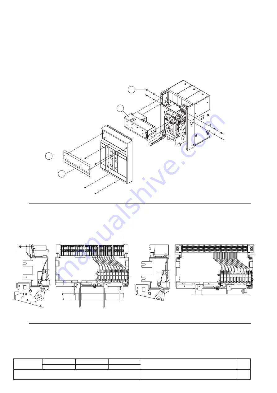
– quitar la protección frontal (3) del relé girando los bloqueos (1) tal
como se indica en la figura;
– tras desenroscar las tuercas laterales (2), quitar el relé de protección
(4) desde el frente del interruptor
Fig. 21
Los contactos auxiliares, siendo de dos vías (contactos en
conmutación), se pueden modificar de contactos de apertura a con-
tactos de cierre y viceversa; para ello, hay que desplazar simplemente
el conductor de salida de una a otra posición de la manera indicada en
la figura.
Fig. 22
(Contacto N.C.)
(Contactos deslizantes)
(N.C. contact)
(sliding contacts)
b) Contactos de posición
Para cambiar el estado del contacto de posición, proceder de la manera
descrita para los contactos auxiliares (véase fig. 21-22).
5.4
Conversion of the auxiliary contacts or position contacts
from normally closed (opening) to normally open (closing)
or vice versa
The contacts are cabled in the factory as shown in the electrical circuit
diagram. Should their state have to be modified due to installation
requirements, proceed as follows:
a) Auxiliary contacts
To access the auxiliary contacts, carry out the following operations:
– remove the front protection (3) of the release working on the locks
(1) as shown in the figure
– remove the protection release (4), by removing the lateral nuts (2)
and sliding it out from the front of the circuit-breaker.
As they are the two-way type (change-over contacts), the auxiliary
contacts can be modified from opening contacts to closing contacts and
vice versa simply by moving the output conductor from one position to
the other, as shown in the figure.
b) Position contacts
To change the state of the contact, proceed in the same way as for the
auxiliary contacts (see figs. 21-22).
1
3
4
2
(Contacto N.A.)
(Placa de bornes)
(N.O. contact)
(terminal box)


