N° Doc.
Doc. No.
Mod.
Rev.
M4379
SACE Emax
601933/003
Aparato
Apparatus
Escala
Scale
N° Pag.
Sh. No.
22/100
7.3
Maniobra de inserción y de extracción
ADVERTENCIAS
a) Antes de efectuar cualquier maniobra de inserción o de extracción,
abrir el interruptor.
b) El interruptor (parte móvil) y parte fija están dotados con un bloqueo
que impide la introducción en la parte fija de interruptores con
corriente nominal diferente: el operador tiene que controlar, antes
de efectuar la maniobra de inserción, que el bloqueo antiintroducción
sea correcto para evitar solicitaciones inútiles.
c ) Antes de la maniobra de inserción quitar el bloqueo por candados
de los obturadores de aislamiento de los terminales de secciona-
miento en la parte fija.
NOTA
El interruptor (parte móvil) puede presentar, con respecto a la parte
fija, diferentes posiciones identificadas de la manera siguiente:
– EXTRAÍDO: la parte móvil se encuentra insertada en la parte fija SIN
la conexión entre los terminales de potencia y SIN la conexión de los
contactos deslizantes para los circuitos auxiliares: en esta posición no
es posible efectuar ninguna maniobra eléctrica del interruptor; en el
frente, el indicador (9, fig. 23) señala DISCONNECTED y la puerta de
la celda del cuadro se puede cerrar.
– SECCIONADO EN PRUEBA: la parte móvil se encuentra insertada
en la parte fija SIN la conexión entre los terminales de potencia, pero
CON la conexión de los contactos deslizantes para los circuitos
auxiliares: en esta posición sólo se pueden efectuar las maniobras
para pruebas con el interruptor quitado. El indicador (9, fig. 23) señala
TEST ISOLATED.
– INSERTADO: la parte móvil se encuentra completamente insertada
en la parte fija CON la conexión entre los terminales de potencia y de
los contactos deslizantes para los circuitos auxiliares; el interruptor se
encuentra en condiciones de funcionamiento; el indicador (9, fig. 23)
señala CONNECTED.
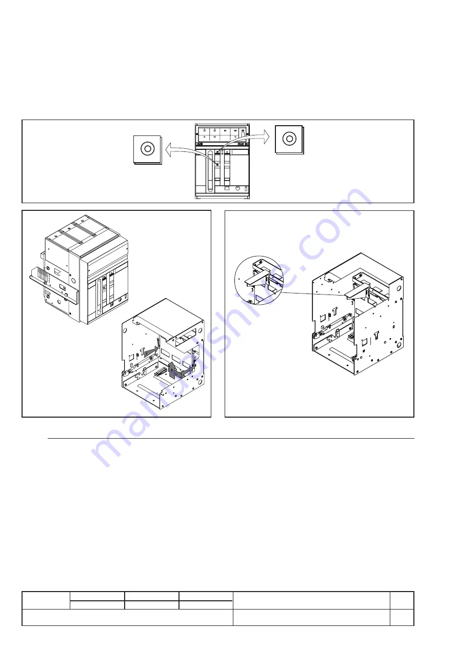
Fig. 28
7.3
Racking-in and racking-out operations
CAUTION
a) Open the circuit-breaker before carrying out any racking-in or
racking-out operation.
b) The circuit-breaker (moving part) and fixed part are fitted with a lock
which prevent insertion of the fixed part of circuit-breakers with
different rated current: the congruency of the anti-insertion lock
must be checked by the operator before carrying out the racking-
in operation to prevent unwarranted stresses.
c ) Before the racking-in operation, remove any padlocks from the
segregation shutters of the isolating terminals on the fixed part.
NOTE
The circuit-breaker (moving part) can take up different positions in
relation to the fixed part, identified as follows:
– RACKED-OUT: the moving part is connected in the fixed part
WITHOUT connection between the power terminals and WITHOUT
coupling of the sliding contacts for the auxiliary circuits: in this position
all circuit-breaker electrical operations are prevented. On the front,
the indicator (9, fig. 23) indicates DISCONNECTED; the switchboard
compartment door can be closed.
– TEST DISCONNECTED: the moving part is racked into the fixed part
WITHOUT connection between the power terminals, but WITH
coupling of the sliding contacts for the auxiliary circuits. In this position
the circuit-breaker can be operated for the no-load tests. The
indicator (9, fig. 23) indicates TEST ISOLATED.
– RACKED-IN: the moving part is completely racked into the fixed part
WITH connection of both the power terminals and the sliding contacts
for the auxiliary circuits. The circuit-breaker is in operating condi-
tions. The indicator (9, fig. 23) indicates CONNECTED.
Pulsar
Push
A
B
C


