1SDH002031A1002 ECN000092998 Rev. B
SACE Tmax XT2
– XT4 | 36
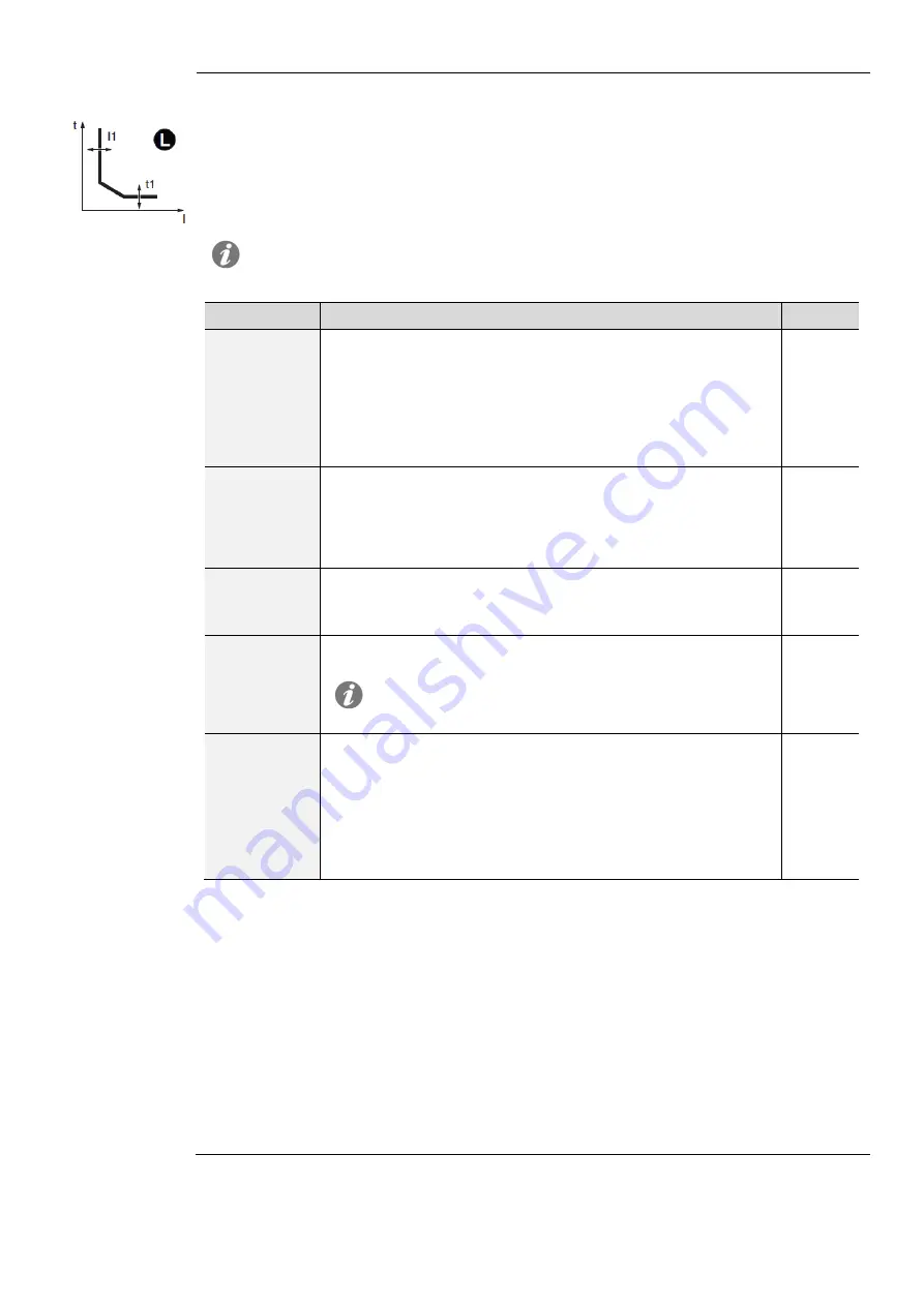
L Protection
Function
If the current of one or more phases exceeds the I1 threshold, the protection is activated and,
after a time determined by the value read and the parameters set, it sends the TRIP command.
To verify and simulate the trip times based on all the parameters, see:
Protection summary table with the formulas for calculations (page 78)
Chart with tripping curve (pages 81, 82, 83)
Parameters
NOTE: the Ekip M Touch Trip unit has default constraints and parameters that are
different from the other models. The details are shown after the table.
Parameter
Description
Default
Curve
Determines curve dynamic and calculation of trip time:
t=k/I
2
in accordance with IEC 60947-2
IEC 60255-151 SI
IEC 60255-151 VI
IEC 60255-151 EI
t=k/I
4
in accordance with 60255-151
t= k/I
2
Threshold I1
Defines the value that activates protection and contributes to
calculating trip time.
The value is expressed both as an absolute value (Ampere) and
as a relative value (In), settable in a range:
0.4 In .. 1In with 0.001 In step.
1 In
Time t1
Contributes to calculating trip time.
The value is expressed in seconds, which are settable in a range:
3 s .. 60 s, with 1 s step.
60 s
Thermal
memory
Activates/deactivates the thermal memory function, see page 70
for details
NOTE: the function is always ON with Ekip M Touch trip
unit and available for all the others Trip unit model with a
curve t=k/I
2
OFF
Pre-alarm I1
Enables a warning to be sent that the measured current is near
the threshold triggering the protection.
The value is expressed as a percentage of the threshold I1, which
is settable in a range: 50 % I1 .. 90 % I1, with 1 % step.
The pre-alarm threshold is deactivated in two cases:
current below pre-alarm threshold I1
current above threshold I1
90 % I1
Ekip M Touch
L protection of the Ekip M Touch differs with the other models in the following ways:
Curve:
cannot be changed and is specific for Ekip M Touch (see page 84)
Time t1:
cannot be changed and is determined by the
trip class
(see page 66)
Thermal memory:
always enabled, operating according to IEC 60255-8; thermal memory
reset time set by the
trip class
(see page 66)
Different default parameters: I1 =
0.4 In
; t1 =
45 s (
Class =
20E)
Constraints, limitations, and additional functions
The I1 threshold must be less than the I2 threshold (if the S protection is active)
The protection trip time is forced to 1 s if the calculations result in a lower theoretical value
and/or if the current detected is higher than 12 In
Summary of Contents for SACE Tmax XT2
Page 84: ...1SDH002031A1002 ECN000092998 Rev B SACE Tmax XT2 XT4 84 L curve Ekip M Touch S curve t k I2 ...
Page 86: ...1SDH002031A1002 ECN000092998 Rev B SACE Tmax XT2 XT4 86 G curve t k I2 G curve t k ...
Page 87: ...1SDH002031A1002 ECN000092998 Rev B SACE Tmax XT2 XT4 87 IU curve UV curve UV2 curve ...
Page 88: ...1SDH002031A1002 ECN000092998 Rev B SACE Tmax XT2 XT4 88 OV curve OV2 curve VU curve ...
Page 89: ...1SDH002031A1002 ECN000092998 Rev B SACE Tmax XT2 XT4 89 S V curve S2 V curve RV curve ...
Page 90: ...1SDH002031A1002 ECN000092998 Rev B SACE Tmax XT2 XT4 90 UF curve UF2 curve OF curve OF2 curve ...
Page 91: ...1SDH002031A1002 ECN000092998 Rev B SACE Tmax XT2 XT4 91 RP curve D curve ...
Page 92: ...1SDH002031A1002 ECN000092998 Rev B SACE Tmax XT2 XT4 92 OQ curve OP curve ...
Page 93: ...1SDH002031A1002 ECN000092998 Rev B SACE Tmax XT2 XT4 93 UP curve RQ curve ...
Page 94: ...1SDH002031A1002 ECN000092998 Rev B SACE Tmax XT2 XT4 94 ROCOF curve R JAM curve R STALL ...
Page 95: ...1SDH002031A1002 ECN000092998 Rev B SACE Tmax XT2 XT4 95 UC curve ...


