12
Auxiliary outputs
The annunciator includes four auxiliary output
relays. Two output relays act as group alarm
reflash output elements, one auxiliary output
relay is dedicated for control of an audible device
and one relay acts as an auxiliary output element
for the internal self-supervision function.
Channel 1
Channel 2
Grouping
A
B
A
B
Channel 15
Channel 16
A
B
A
B
Selection of reflash type
0 = FCRF
1 = AACR
2 = PSR
3 = FCFR + ISR
Group reflash 1
Group reflash 2
Selection of reflash type
0 = FCFR
1 = AACR
2 = ISR
3 = FCFR + ISR
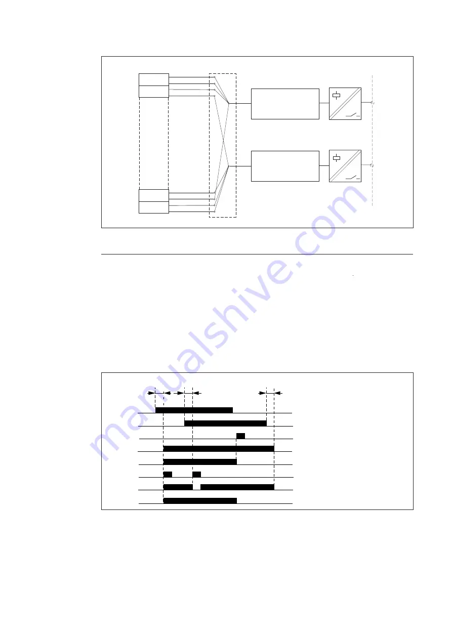
Fig. 10. Principle diagram of reflashes.
Group alarm
reflash signals
Each alarm channel generates two reflash out-
put signals, A and B, which can be freely linked
to the two reflash output relays to form two
group alarm reflash functions. The two group
alarm reflash output relays can be given one of
the following modes of operation selectable by
programming, separately for both of the output
relays:
0 = FCFR, Field Contact Following Reflash
1 = AACR, Acknowledge Action Controlled
Reflash
2 = ISR, Impulse Shaping Reflash
3 = FCFR + ISR, Field Contact Following Reflash
with a 300 ms interruption of the reflash
signal any time a new alarm signal joins in an
already active group alarm bunch
4 = FCFR + AACR, Field Contact Following
Reflash and Action Controlled Reflash (se
figure below)
Fig. 11. Principle diagram for the different reflash signal types. The alarm signals 1 and 2 are grouped
to the same group alarm reflash signal.
NOTE! The reflash signals are always accompa-
nied by a certain basic delay. The basic delay
time depends on the number of incoming alarm
signals per time unit and on the number of
internal interlocking levels in use. The basic
time delay of the reflash signal is 70 ms if only
one alarm signal is received within a time period
of 200 ms and if no interlockings are used.
Channel input delays
Channel reset delay
Alarm 1
Alarm 2
Acknowledge
Signal following
Alarm memory following
Pulse type
Signal following with break
FCFR + AACR


