16
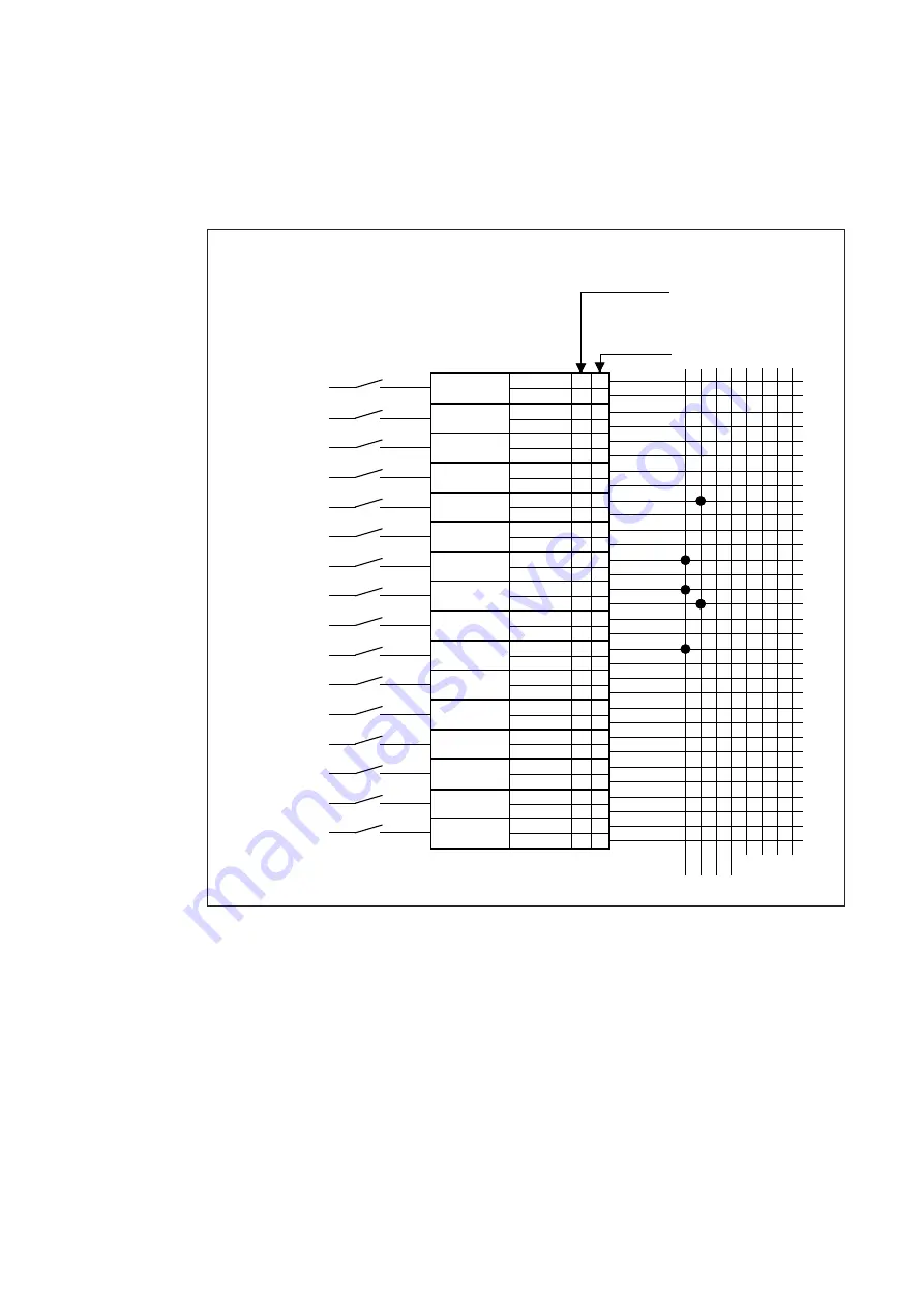
The connections described above have been
marked with dots on the corresponding lines in
figure 15. The programming technique using
the push-buttons on the front panel is described
on page 30.
To give a good overview of the interlocking
configuration the figure 15 can be used when
configuring the interlocking scheme.
Example of channel
interlocking
configuration
An external interlocking signal is connected to
input channel 10 which is configured to give a
interlocking output to interlocking line 1. When
active, line 1 interlocks reflash signal type A on
channel 7 and locks channel 8 totally. Channel
8 gives also an interlocking output to line 2
which in turn interlocks reflash signal type A on
channel 5.
Fig. 15. Interlocking diagram.
INTERLOCKING GROUPS
1 2 3 4
5 6 7 8
Channel 1/__
Function 1
Function 2
Channel 2/__
Function 1
Function 2
Channel 3/__
Function 1
Function 2
Channel 4/__
Function 1
Function 2
Channel 5/__
Function 1
Function 2
Channel 6/__
Function 1
Function 2
Channel 7/__
Function 1
Function 2
Channel 8/__
Function 1
Function 2
Channel 9/__
Function 1
Function 2
Channel 10/__
Function 1
Function 2
Channel 11/__
Function 1
Function 2
Channel 12/__
Function 1
Function 2
Channel 13/__
Function 1
Function 2
Channel 14/__
Function 1
Function 2
Channel 15/__
Function 1
Function 2
Channel 16/__
Function 1
Function 2
TYPE OF INTERLOCKING
0 = interlocking output
1 = reflash A interlocking input
2 = channel interlocking input
Alarm module No___
Interlocking input
0
1
2 1
0 2
1
1
1 2


