background image

10.2 Cyclic Brake Check guidelines

About Cyclic Brake Check

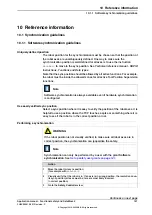
If using Cyclic Brake Check on a SafeMove system, then Cyclic Brake Check should
be configured in the safety configuration, see

Configuring Cyclic Brake Check on

page 169

The brake check must then be performed regularly (within the configured

time interval).

Prerequisites for brake test

The robot and all additional axes must be moved to a safe and relaxed
position (away from people, equipment and not too much stretched) before
performing Cyclic Brake Check. Normally the robot moves only a few
centimeters during the brake tests.

Move the robot to a stop point before performing Cyclic Brake Check.

Cyclic Brake Check can only be performed at normal execution level (not
from a trap routine, error handler, event routine or store path level).

Brakes are tested in consecutive order and each test takes 10-15 seconds.

Do not change the speed from the FlexPendant and do not use

VelSet

,

AccSet

,

SpeedRefresh

, or any other instruction that affects motion

performance in

TRAPS

or event routines while

CyclicBrakeCheck

is active.

Note

The RAPID function

IsBrakeCheckActive

can be used to check if

CyclicBrakeCheck

is active.

Note

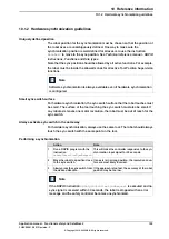
If Cyclic Brake Check is called together with the below combinations, then Cyclic
Brake Check will be executed for all axes and the safety controller will not take
any actions when the Cyclic Brake Check interval has passed or if the Cyclic
Brake Check fails:

SafeMove system with an empty safety configuration.

SafeMove system with a safety configuration, but without a configured Cyclic
Brake Check.

Performing Cyclic Brake Check

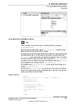
Start the brake check from RAPID

Call the procedure

CyclicBrakeCheck

.

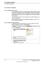
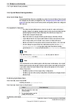
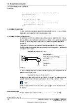
Start the brake check from the FlexPendant

Note/illustration

Action

Move the robot to a safe brake
check position.

1

On the FlexPendant, open the

Safety Controller

view.

2

Continues on next page

200

Application manual - Functional safety and SafeMove2

3HAC052610-001 Revision: P

© Copyright 2016-2020 ABB. All rights reserved.

10 Reference information

10.2 Cyclic Brake Check guidelines

Summary of Contents for SafeMove2

Page 1: ...ROBOTICS Application manual Functional safety and SafeMove2 ...

Page 2: ...Trace back information Workspace 20C version a3 Checked in 2020 09 14 Skribenta version 5 3 075 ...

Page 3: ...Application manual Functional safety and SafeMove2 RobotWare 6 11 02 Document ID 3HAC052610 001 Revision P Copyright 2016 2020 ABB All rights reserved Specifications subject to change without notice ...

Page 4: ...ty by ABB for losses damage to persons or property fitness for a specific purpose or the like In no event shall ABB be liable for incidental or consequential damages arising from use of this manual and products described herein This manual and parts thereof must not be reproduced or copied without ABB s written permission Keep for future reference Additional copies of this manual may be obtained f...

Page 5: ... 46 2 5 Supervision functions 46 2 5 1 Stand Still Supervision SST 48 2 5 2 Axis Speed Supervision ASP 49 2 5 3 Tool Speed Supervision TSP 51 2 5 4 Axis Position Supervision APO 53 2 5 5 Tool Position Supervision TPO 54 2 5 6 Tool Orientation Supervision TOR 55 2 5 7 Control Error Supervision 57 3 Installation 57 3 1 Hardware 57 3 1 1 Safety module 58 3 1 2 Sync switch 59 3 2 Software 60 3 3 Safe ...

Page 6: ...on tab 135 5 3 4 The Safe Ranges tab 137 6 Configuring SafeMove 137 6 1 Recommended working procedure 139 6 2 Preparations 140 6 3 Configure system parameters 141 6 4 Set up safety user grants 143 6 5 Starting Visual SafeMove 144 6 6 Configure Manual Operation Supervision 145 6 7 Configure the robot 147 6 8 Configure additional axes 148 6 9 Configure the synchronization position 149 6 10 Configure...

Page 7: ...ervo Lag 210 10 4 Connection of external emergency stop 212 10 5 SafeMove geometry configuration file 212 10 5 1 Introduction 214 10 5 2 Use cases 216 10 5 3 Explanation of the configuration file 216 10 5 3 1 Introduction 218 10 5 3 2 Drive module configuration 219 10 5 3 3 Robot data 221 10 5 3 4 External axis 222 10 5 3 5 Tool 225 10 5 3 6 Safe zones 227 10 5 4 Example 230 10 6 How to establish ...

Page 8: ...This page is intentionally left blank ...

Page 9: ...llation work working with industrial robots using RobotStudio personal safety see Safety manual for robot Manipulator and IRC5 or OmniCore controller References Document ID Reference 3HAC051016 001 Application manual Additional axes and stand alone controller 3HNA026812 Application manual Functional safety and SafeMove for paint 3HAC065546 001 Application manual PROFINET Controller Device For Robo...

Page 10: ...put button on page 83 Minor corrections B Released with RobotWare 6 04 01 Updated section Safe fieldbus parameters on page 92 Updated section The Keyless Mode Selector on page 118 Added section Reset safety controller to factory settings on page 187 Updated section Cyclic Brake Check guidelines on page 200 Added section Connection of external emergency stop on page 210 Minor corrections C Released...

Page 11: ...otWare 6 07 Changed manual name to indicate that it covers the function SafeMove2 and not SafeMove1 SafeMove now supports Stand alone controller with some restrictions See Limitations on page 27 Updated picture of FlexPendant user interface in section The Safety Controller control panel on page 113 IRB 6700Inv added to supported robots Some functionality regarding PROFIsafe is moved to I O Configu...

Page 12: ...ivities on page 193 Added limitation for Electronically linked motors see Electronically linked motors on page 30 M Released with RobotWare 6 11 Stand Still Supervision is now possible in manual mode see Configuring Stand Still Supervision on page 166 The service mode is updated see The Mode tab on page 115 Changes regarding Basic joint supervision made in section Limitations on page 27 Overview o...

Page 13: ...nce information safety standards unit conversions screw joints lists of tools Spare parts list with corresponding figures or references to separate spare parts lists References to circuit diagrams Technical reference manuals The technical reference manuals describe reference information for robotics products for example lubrication the RAPID language and system parameters Application manuals Speci...

Page 14: ... are aimed at those having first hand operational contact with the product that is production cell operators programmers and troubleshooters 14 Application manual Functional safety and SafeMove2 3HAC052610 001 Revision P Copyright 2016 2020 ABB All rights reserved Product documentation Continued ...

Page 15: ...ou are familiar with the safety information in the product manuals for the robot The integrator of the robot system is responsible for the safety of the robot system Application manual Functional safety and SafeMove2 15 3HAC052610 001 Revision P Copyright 2016 2020 ABB All rights reserved Safety ...

Page 16: ...This page is intentionally left blank ...

Page 17: ...ent safety by supervising the position Tool Position Supervision speed Tool Speed Supervision and orientation Tool Orientation Supervision of the tool Tool supervision functions Protects the surroundings by supervising the axis position Axis Position Supervision and the axis speed Axis Speed Supervision Axis supervision functions Supervises the stand still of robot axes without having to switch th...

Page 18: ...ure and visualize supervision functions in a 3D environment configure stop functions such as automatic stop configure Cyclic Brake Check configure safe signals safe Ethernet communication and I Os configure signal logics configure system status outputs SafeMove Basic and SafeMove Pro The below table lists the differences between SafeMove Basic and SafeMove Pro SafeMove Basic SafeMove Pro Function ...

Page 19: ...ality in SafeMove requires correct settings of payload and additional axes since this will affect the calculated accepted servo lag Please also note that external forces applied on the manipulator can cause a negative influence on the supervision functions since the servo lag might differ from the calculated values due to such external forces DANGER A SafeMove configuration must always be validate...

Page 20: ...hapter we describe how the safety module and SafeMove comply with relevant safety standards and regulations Note The safety module and SafeMove is only a part of the robot system it is the responsibility of the user to do a risk assessment of the robot system It is also the responsibility of the user of SafeMove to ensure that the robot system is designed and installed in accordance with the safet...

Page 21: ...ments EN ISO 10218 1 2011 Robots for industrial environments Safety requirements Part 1 Robot EN 61000 6 2 2005 EMC Generic immunity EN 61000 6 4 2007 A1 2011 EMC Generic emission EN ISO 13849 1 2015 Safety of machinery Electrical equipment of machines Part 1 General requirements EN ISO 13849 2 2012 Safety of machinery Safety related parts of control systems Part 2 Validation Application manual Fu...

Page 22: ...he safety function is always performed and a safe state shall be maintained until the detected fault is corrected All reasonably foreseeable faults shall be detected This requirement is considered to be equivalent to structure category 3 as described in ISO 13849 1 Category 3 is normally fulfilled by redundant circuits such as dual channels which is the case for SafeMove SafeMove together with the...

Page 23: ...function as described above It is important to ensure that the safety controller and the robot controller are synchronized The safe sync position is defined during configuration and stored in the safety controller In this position SafeMove will calculate the robot joint positions and check against a stored value to confirm that the synchronization is correct covering the following points SafeMove ...

Page 24: ...e area the supervision functions will stop the robot or set an output signal To ensure that also this supervision complies with the category 3 requirement SafeMove is internally working with a two channel microprocessor based system Both processors make parallel calculations comparing the actual position and the reference position 24 Application manual Functional safety and SafeMove2 3HAC052610 00...

Page 25: ... assessed that the software blocks implementing safety functions as defined in ISO 10218 1 2011 are correctly implemented Certifications by UL The safety controller DSQC1015 and included software is approved by UL according to the following standards UL 1740 Standard for Robots and Robotic Equipment ANSI RIA R15 06 Industrial Robots and Robotic Systems CAN CSA Z434 14 Industrial Robots and Robot S...

Page 26: ... third party certifications the safety module and SafeMove fulfills all relevant current safety standards globally 26 Application manual Functional safety and SafeMove2 3HAC052610 001 Revision P Copyright 2016 2020 ABB All rights reserved 1 Introduction 1 2 6 Conclusion ...

Page 27: ...s mode selector options are available for the following controller variants Single controller 700 3 Robots supported by SafeMove From RobotWare 6 09 the following robot families are supported by SafeMove under the condition that the robot version is supported by RobotWare 6 09 IRB 140 140T IRB 260 IRB 460 IRB 660 IRB 760 IRB 1200 Type B IRB 1400 1410 IRB 1520ID IRB 1600 1660 IRB 2400 IRB 2600 IRB ...

Page 28: ... to have a supported robot as the main product In the Safety configuration exclude not supported robots by use setting Exclude from configuration For more information see Application manual Functional safety and SafeMove2 WARNING Even if a model is supported by SafeMove each installed robot must be verified individually to ensure that no mechanical or other deviations exists which would make SafeM...

Page 29: ...upper and lower work area limitations for additional axes Track unit length arm side max 448 m Rotating axis arm side max 25700 degrees or 448 radians On the motor side there is also a limitation of 32000 revolutions Combined external axes and robot with gantry SafeMove does not support supervision of combined external axes such as a gantry or supervision of robots moved by the gantry It is possib...

Page 30: ...e possible but the tool supervision functions are not supported No deactivation Additional axes that are used with activation deactivation feature are not supported If additional axes are to be used they must also be active at all times Independent joint Independent joint cannot be monitored by SafeMove Electronically linked motors SafeMove supports supervision of additional axes using Electronica...

Page 31: ...odule Note If a supervision function triggers a stop on one robot in a MultiMove system then all robots in the MultiMove system will be stopped Responsive jogging Category 1 stop is deactivated in manual mode when responsive jogging is active This is because a robot that is stopped with a category 1 stop follows its programmed path while decelerating When using responsive jogging there is no defin...

Page 32: ...the actuators to achieve the stop Power is removed from the actuators when the stop is achieved Category 1 stop A robot that is stopped with a category 1 stop follows its pro grammed path while decelerating Safe for a person to be in an area Occupationally safe Safe for the machinery but not safe for persons to enter the area Operationally safe Dual monitored digital input Safe input Dual monitore...

Page 33: ... Axis Position Supervision APO Axis Speed Supervision ASP Contact Application Tolerance CAP Stand Still Supervision SST Tool Orientation Supervision TOR Tool Position Supervision TPO Tool Speed Supervision TSP Application manual Functional safety and SafeMove2 33 3HAC052610 001 Revision P Copyright 2016 2020 ABB All rights reserved 1 Introduction 1 5 Abbreviations and acronyms ...

Page 34: ...This page is intentionally left blank ...

Page 35: ...ns Supervision functions can be activated and deactivated with safe input signals or be configured to be permanently active The supervision functions can stop the robot and additional axes or set a safe output signal if a violation occurs Status Signal The signal is set to 0 for activation Activation The signal is set to 1 when active Function active status The signal is set to 0 at violation Note...

Page 36: ... category 1 stop is changed so that SafeMove supervises that all robot axes will stop within 1 second For information on how to select Basic joint supervision mode see Robot parameters node on page 87 Exclude from configuration In the implementation of the safety controller some safety supervision functions are included in the system even if the SafeMove option is not selected This includes Safe B...

Page 37: ... configuration see Robot parameters node on page 87 DANGER A SafeMove configuration must always be validated to verify that the desired safety is achieved If no validation is performed or the validation is inadequate the configuration cannot be relied on for personal safety Application manual Functional safety and SafeMove2 37 3HAC052610 001 Revision P Copyright 2016 2020 ABB All rights reserved 2...

Page 38: ...jogging can be resumed DANGER If Basic joint supervision mode is used the supervision of the TCP WCP and elbow speed is disabled Instead axis speeds are supervised with limits set to approximate a Cartesian speed limit corresponding to the parameter Max speed in manual mode The user is responsible for validating that this speed limit satisfies the requirements for safe manual mode operation If the...

Page 39: ...ll axes must be within the defined range to be able to activate the relaxed control error For zones both reference value and measured value for the TCP must be within the defined zone to be able to activate the relaxed control error Up to 9 axes can be supervised simultaneously WARNING When the Contact Application Tolerance is active then the dual channel safety tolerance is reduced with the confi...

Page 40: ...ion Tolerance is not considered to be active if the run chain is open Related information Control Error Supervision on page 55 40 Application manual Functional safety and SafeMove2 3HAC052610 001 Revision P Copyright 2016 2020 ABB All rights reserved 2 SafeMove functions 2 2 2 Contact Application Tolerance CAP Continued ...

Page 41: ...te The supervision functions can only be active while SafeMove is synchronized When unsynchronized only manual mode operation with reduced speed is possible until synchronization is executed successfully Settings The following settings need to be configured for software synchronization Status signal Angles and positions of robot and additional axes at the synchronization position Dependencies to o...

Page 42: ...is assumed to be correct If the synchronization is correct the safety controller then sends a message to the robot controller confirming that the safety controller is synchronized to its mechanical units and continues with its regular operation Note The supervision functions can only be active while SafeMove is synchronized When unsynchronized only manual mode operation with reduced speed is possi...

Page 43: ... page 199 Recovery after safety violation on page 191 Application manual Functional safety and SafeMove2 43 3HAC052610 001 Revision P Copyright 2016 2020 ABB All rights reserved 2 SafeMove functions 2 3 2 Hardware synchronization Continued ...

Page 44: ...ion mode is used the Safe Brake Ramp supervision is changed to supervise that all robot axes will stop within exactly 1 second Settings For track motions and other additional axes the parameters Brake Ramp Limit and Ramp Delay have to be set The parameter Start Speed Offset is used for both manipulator and all additional axes Function activation Safe Brake Ramp cannot be dynamically activated deac...

Page 45: ...y on page 32 Explanation of Safe Brake Ramp on page 90 Application manual Functional safety and SafeMove2 45 3HAC052610 001 Revision P Copyright 2016 2020 ABB All rights reserved 2 SafeMove functions 2 4 1 Safe Brake Ramp Continued ...

Page 46: ...rmance level PL e which is not provided by SafeMove If this kind of work is intended the risk must be added to the risk analysis of the installation and eliminated by other means for example additional mechanical stops DANGER It is not allowed to enter the working space of the robot if a Contact Application Tolerance function is active even if a Stand Still Supervision function is active at the sa...

Page 47: ...is permanently active if only output signal and no stop is used Note If SafeMove becomes unsynchronized the robot will stop and the Stand Still Supervision function will be deactivated A movement with reduced speed is possible Limitations Stand Still Supervision is only available for SafeMove Pro see Functional safety options on page 18 Application manual Functional safety and SafeMove2 47 3HAC052...

Page 48: ...a zone for which the Axis Speed Supervision is applied Which axes to supervise Maximum speed and minimum speed defined per axis Category 0 stop category 1 stop or no stop if a violation occurs Set an output signal if a violation occurs Set a status signal when the function is active Assignment of safe input for activation of Axis Speed Supervision How to define these settings is described in Confi...

Page 49: ...nding on the configuration There can be up to 8 global sets of Tool Speed Supervision plus one for each zone and axis range up to 16 zones and 8 axis ranges WARNING Tool Speed Supervision is not active in manual operating mode and shall therefore not be used to guarantee operator safety in that mode CAUTION Since the TCP speed is determined by the programmed speed it is very important that the TCP...

Page 50: ... the Tool Speed Supervision is applied Maximum allowed speed in mm s for TCP elbow and speed supervised points An optional minimum speed for the TCP Category 0 stop category 1 stop or no stop if a violation occurs Set an output signal if a violation occurs Set a status signal when the function is active Assignment of a safe input for activation or set as permanently active How to define these sett...

Page 51: ...ers can be configured for Axis Position Supervision A safe range to which it should be applied Category 0 stop category 1 stop or no stop if an axis is outside its range Set an output signal if an axis is outside its range Set a status signal when the function is active Assignment of safe inputs for activation of each set of axis ranges or set as permanently activated How to define these settings ...

Page 52: ...d ranges B Robot position C Axis 2 is within the allowed range but axis 3 is not within its allowed range This will trigger a violation C Note The ranges define axis angles not the position of the TCP In robot position C the TCP is still within what seems to be a safe range but axis 3 is outside its defined range Limitations WARNING Be aware of that the braking starts when the axis exceeds the con...

Page 53: ...violates its zone limits Set an output signal if the robot violates its zone limits Set a status signal when the function is active If the upper arm should be included in the supervision or only the tool If the robot should be allowed only inside or only outside of the zone How to define these settings is described in Configuring Tool Position Supervision on page 160 Function activation Tool Posit...

Page 54: ...n be configured for Tool Orientation Supervision An optional axis range or a zone for which the Tool Orientation Supervision is applied Allowed orientation of the tool in x and z directions including a tolerance Assignment of a safe input for activation or set as permanently active Category 0 stop category 1 stop or no stop if a violation occurs Set an output signal if the tool orientation violate...

Page 55: ...or Supervision is activated automatically after the safety controller has been synchronized with the robot position When Control Error Supervision triggers the following happens The robot is stopped with a category 1 stop An event log message 90511 is sent to the robot controller Illustration of control error en0700000723 Function activation Control Error Supervision is always active It can only b...

Page 56: ...This page is intentionally left blank ...

Page 57: ...e the IRC5 main computer unit For information on how to install the Safety module see Product manual IRC5 B A xx1500001760 Safety module DSQC1015 A PCIexpress slot for other devices B Application manual Functional safety and SafeMove2 57 3HAC052610 001 Revision P Copyright 2016 2020 ABB All rights reserved 3 Installation 3 1 1 Safety module ...

Page 58: ...d to a safety PLC and communicate with the robot controller via PROFIsafe Safety PLC Sync switch PROFIsafe Safety controller Robot Controller xx1600000249 58 Application manual Functional safety and SafeMove2 3HAC052610 001 Revision P Copyright 2016 2020 ABB All rights reserved 3 Installation 3 1 2 Sync switch ...

Page 59: ... 3 For more information see Operating manual RobotStudio Note RobotStudio must be of the same version or later than the RobotWare used Create a robot system A RobotWare license with the option SafeMove Basic or SafeMove Pro is required to run SafeMove on the robot controller Use RobotStudio to configure build and download a RobotWare system to the robot controller For more information see Operatin...

Page 60: ... make sure the safety is maintained throughout the solution e g signal redundancy safe PLC programming safe state at power failure etc DANGER An emergency stop on the controller will not be forwarded to the safety PLC or any other equipment if the robot controller is disconnected DANGER The emergency stop buttons on a disconnected robot controller must be clearly marked or covered CAUTION The repl...

Page 61: ...ss provided by the network administrator LAN 2 can only be configured as private networks to the IRC5 controller LAN 3 can be configured either as an isolated LAN3 network or as part of the private network Limitations If the input or output size on the internal device for PROFINET or EtherNet IP is changed then the safety configuration needs to be re loaded to the robot controller Do not create st...

Page 62: ...d safe I O devices on PROFINET or EtherNet IP networks In future releases it will also support other networks For more information see Application manual PROFINET Controller Device or Application manual EtherNet IP Scanner Adapter 62 Application manual Functional safety and SafeMove2 3HAC052610 001 Revision P Copyright 2016 2020 ABB All rights reserved 3 Installation 3 3 2 The I O Engineering Tool...

Page 63: ...apter device is configured the safe fieldbus must be configured in the Visual SafeMove user interface in RobotStudio see Safe fieldbus parameters on page 92 and Configure safe I O on page 152 Tip For an example on how to configure a PLC to communicate with the robot controller see section How to establish CIP Safety communication with a PLC on page 230 Note The user is required to clear any pre ex...

Page 64: ... hijacking an input resource in a validated safety system Only one owner is allowed It is possible to reset the ownership by executing the reset CIP Safety function from the FlexPendant which resets all persistent memory of the adapter see Reset CIP Safety on page115 After controller restart the CIP Safety configuration will be restored except from the ownership Note It is the responsibility of th...

Page 65: ...otWare license with the options PROFINET Controller Device or PROFINET Device and PROFIsafe F Device or PROFIsafe F Host Device is required to run PROFIsafe F Device on the robot controller Installation For information on how to connect and configure the PROFINET industrial network see Application manual PROFINET Controller Device Application manual Functional safety and SafeMove2 65 3HAC052610 00...

Page 66: ... where each slot can have maximum 8 byte Install and configure safe I O devices For information on how to connect and configure the safe I O devices see Application manual PROFINET Controller Device Operator acknowledge There are two ways to acknowledge a change in the PROFIsafe communication for example if the communication cable was disconnected and reconnected By tapping the F Host Op Ack butto...

Page 67: ...etting up the ABB S500 safe I O devices is included by default in the I O Engineering Tool For more information see Product specification Controller IRC5 the application note Unbundled S500 Safety I Os 3ADR024128K0201 and abb com plc Limitations This option is using PROFIsafe F Host but it does not have full F Host functionality since it is limited to the specific safe I O devices from ABB Install...

Page 68: ...hus it is absolutely necessary to use other means of safety to maintain the requirements of the standard and the machinery directive and also to make a risk assessment of the completed cell Such additional arrangements and risk assessment is the responsibility of the system integrator and the system must not be put into service until these actions have been completed DANGER A recommendation is to ...

Page 69: ...t requested xx1700000465 Mode change to manual reduced speed mode The robot controller will change to manual reduced speed mode when all of the following conditions apply Manual reduced speed is requested Remote control enable is active xx1700000467 Continues on next page Application manual Functional safety and SafeMove2 69 3HAC052610 001 Revision P Copyright 2016 2020 ABB All rights reserved 3 I...

Page 70: ...rror handling If the PLC requests a mode change when the remote control enable signal is not active then an event log is issued and the mode remains unchanged If the requested operating mode differs from the actual mode then robot motion is prevented If the PLC requests a mode change to automatic mode but does not acknowledges it within 10 seconds then the system is set to manual reduced speed mod...

Page 71: ...uts and outputs can only be defined by editing the I O configuration file they cannot be defined by using the FlexPendant or RobotStudio Use the following procedure to activate the system inputs and outputs Action Save a copy of the I O configuration file eio cfg using the FlexPendant or RobotStudio 1 Edit the I O configuration file eio cfg using a text editor 2 Add the system inputs to the group ...

Page 72: ...This page is intentionally left blank ...

Page 73: ...ation should be used which allows zones to be generated automatically When not running a RobotStudio station Online Monitor is used to visualize the robot Starting Visual SafeMove Action Start RobotStudio with a virtual controller with or without a station or connect a real controller 1 In the Controller tab click Online Monitor 2 Not needed when running a RobotStudio station In the Controller tab...

Page 74: ...indow displays information about events that occur in RobotStudio both general events and Visual SafeMove events Output window E Displays all violations that has occurred since the last restart SafeMove Viola tions window Click a violation in the list to show a detailed view of all geo metries that are related to the violation The geometries that are not related are automatically hidden The violat...

Page 75: ...al SafeMove for editing zones Drag and drop on spheres in the graphics window at corners and surfaces to modify a zone Tip To lock an axis while dragging press x or y on the keyboard Double click vertices or surfaces in the graphics window to create new corners vertices at that location Delete vertices that are no longer desired by selecting and deleting them from the graphics window Move rotate a...

Page 76: ...e From Simulation Simulating SafeMove on page 109 Note The simulation functions are only available when running a Robot Studio station Different tools for analyzing SafeMove configurations Tools The Tools group on page 78 Display options for the Visual SafeMove user interface Options Options group on page 78 Tip Most commands in the ribbon are also available from the Visual SafeMove browser by rig...

Page 77: ...otected elements in the selected file will be imported to the local configuration The protected elements checksum of the local configuration will be the same as the selected files protected checksum after this operation Import protected elements The Controller button Description Button Reads the configuration from the safety controller Read from controller Writes the configuration to the safety co...

Page 78: ...configuration report click Controller and select Write to controller The local report is shown and if you do not want to write it to the controller select Cancel Select Write to controller to overwrite the controller config uration with the RobotStudio configuration Show report The Protected Elements button opens the Protected Ele ments browser Protected Elements From the Protected Elements browse...

Page 79: ...afety signal that activates the selected tool Activation The setting Permanently active is used for a tool that is always active This setting needs to be deactivated to be able to create more than one tool Specifies a safety signal that indicates that the selected tool is active Function active status The setting No signal is used for a tool that is always active Modify the tool data or load a too...

Page 80: ...owing settings are available in the Visual SafeMove Properties browser after the zone has been created Description Setting Used to set the priority for overlapping zones The zone with the highest priority will set the speed limit for the overlapping space BASE lowest priority NORMAL normal priority OVERRIDE highest priority For more information see Configure the zones on page 155 Tip Create a BASE...

Page 81: ...vised angles for that axis will be below the Lower bound and above the Upper bound Invert The Global Functions button The Global Functions button is used to create global safety functions Global safety functions are always active and are not connected to a specific safe zone or safe range The below functions except Stand Still Supervision can also be assigned to individual safe zones and safe rang...

Page 82: ...nel board A21 is reserved for the IRC5 safety controller and must not be disconnected or used for any other purpose Description Setting Specifies the safety signal that activates the safety stop The signal is set to 0 for activation Trigger signal Specifies a safety signal that indicates that the the safety stop is active The signal is set to 0 when triggered Stop trigger status The setting No sig...

Page 83: ... mode corresponds to the old behavior of the External Power Supply button Signal behavior Follow en abling device in manual mode The safety signal always controls the output in any operating mode Signal behavior Always The Cyclic Brake Check button The Cyclic Brake Check button is used to setup the cyclic brake check function For more information see Cyclic Brake Check guidelines on page 200 Descr...

Page 84: ...ll still cover the original area Expands the zone in all directions except the height Expand Contract The Add Safety Function group The Add Safety Function group is used when creating and configuring safe zone and safe range safety functions The following functions are available for both safe zones and safe ranges Description Button Axis Speed Supervision ASP on page 48 Axis Speed Supervision Cont...

Page 85: ... robot that is stopped with a category 0 stop does not follow its programmed path while decelerating Category1Stop Controlled stop with power available to the actuators to achieve the stop Power is removed from the actuators when the stop is achieved A robot that is stopped with a category 1 stop follows its programmed path while decelerating NoStop Passive monitoring with signaling function only ...

Page 86: ...he active tool in SafeMove corres ponds to the active tool of the robot program Get vectors for active tool button The minimum and maximum speed for the tool Speed limits TSP Specifies if Stand Still Supervision is enabled and the toler ance for each robot joint Tolerances SST 86 Application manual Functional safety and SafeMove2 3HAC052610 001 Revision P Copyright 2016 2020 ABB All rights reserve...

Page 87: ...tor the speed of this point so that it does not exceed 250 mm s in manual reduced speed mode Elbow offset Position X Y Z See Explanation of Elbow offset on page 88 A speed offset for the Safe Brake Ramp function Safe Brake Ramp Data Start Speed Offset For track motions and other additional axes the parameters Brake Ramp Limit and Ramp Delay have to be set The parameter Start Speed Offset is used f...

Page 88: ...ool Speed Supervision The elbow point is given a default value based on robot model This value can be changed in the configuration Specify the elbow point s x y and z offsets relative to the center of robot axis 3 Note that the X value should always be negative z3 zb yb x3 y3 A A xx1300002628 Elbow point A Axis 3 x3 y3 z3 Robot base yb zb Note The values that are entered into Elbow Offset should a...

Page 89: ...onal axis Servo lag For more information see Servo Delay Factor and Servo Lag on page 208 Estimated delay factor between reference position and measured position number of 4 ms units when moving the additional axis See TuneMaster signal number 17 and 18 Servo delay factor For more information see Servo Delay Factor and Servo Lag on page 208 The maximum speed in manual mode Max speed manual mode Br...

Page 90: ...tware synchron ization Activation To use hardware synchronization select the input signal from the sync switch Specifies a safety signal that indicates that the safety con troller is synchronized The signal is set to 1 when synchron ized Synchronization status The setting No signal is used if no signal should be used The axis position values of the robot ROB1 Joint Position The axis position value...

Page 91: ...bot controller and configuration of safety signals for the safe fieldbuses and for global virtual safety signals Signals Configuration for mapping of signals to specific safety status inform ation and functions Function Mappings Configuration of combinatory logic for the safety signals that is to be executed before the safety application AND OR XOR etc Pre Logic Configuration of combinatory logic ...

Page 92: ...able for the option PROFIsafe F Device Description Setting Use a combined input output module with the same Destination Address Use combined in put output module check box The PROFIsafe address Source Address combined with the Destin ation Address uniquely identifies the module Source Address Destination Address When using separate input and output modules they cannot have the same Destination Add...

Page 93: ...es are provided Not used The configuration signature is not used Auto generated An automatically generated signature found under Configuration Signature Date Time and ID in the safety report User generated A user defined signature Alternatively the user can manually write the signature encoded as a 10 bytes long hexadecimal string in the text box below The signature can then be found under Configu...

Page 94: ... packets before a connection is dropped It is recommended to keep the default value 5 Max fault Safety format 0 Auto 1 Base 2 Extended Most devices use the format Extended 2 Format type Number of multipliers of Connection RPI that is allowed before the connection will time out It is recommended to keep the default value 2 Timeout multiplier Number of multipliers of 128 μs CIP Safety time increment...

Page 95: ...nalPowerControlActive ExternalPowerControlFeedback LocalEmergencyStopStatus ManualFullSpeedMode ManualMode DriveEnableFeedback SafetyEnable For a description of the safety functions see Description of safety functions on page 97 Accessing safe signals and feedback signals The input output and global signals are automatically made available in RAPID The signals can be found together with all other ...

Page 96: ...Adapter are located on the EN_Internal_Device_Safe on the EthernetIP bus 96 Application manual Functional safety and SafeMove2 3HAC052610 001 Revision P Copyright 2016 2020 ABB All rights reserved 4 The Visual SafeMove user interface in RobotStudio 4 6 2 Signals view Continued ...

Page 97: ...gnal alias gets its value updated i e Safe local I O is first and Safety system is after the pre logic True or false Mandatory Some mappings are mandatory since they are used by the safety controller See Description of safety functions on page 97 Description Displays error for example when the mapping for a mandatory function is missing Errors Note ExtComShutdownAck and SafetyEnable has no source ...

Page 98: ...peed mode is selected ManualFullSpeedMode True if the power to the motors is enabled DriveEnableFeedback The SafetyEnable function should when possible be con nected to a safe input signal from for example a PLC This signal shall be set to True as soon as communication is up and running SafetyEnable When False all signal activated supervision functions such as stop configurations will be deactivat...

Page 99: ...ors can be combined into complex statements Global signals can automatically be created from the statements by clicking Create signals xx1600000054 Note Signals between blocks are created internally and will not be available to the user For example the signal between the OR and the AND block in the above picture Tip First use the button Create signals to automatically create global signals from th...

Page 100: ... INT32 Syntax example Description Operator Destination Source1 Source2 Add integer value Destination Source1 Source2 Subtract integer value Destination Source1 Source2 Multiply integer value Destination Source1 Source2 Divide integer value See also the operator DIV Note Division by zero is undefined If the denominator is zero then the quotient keeps its current value Destination Source1 Source2 Co...

Page 101: ...es with boolean error flag when dividing with zero Note Division by zero is undefined If the denominator is zero then the quotient keeps its current value DIV Filters signal on edge EDGE 0 when trigger signal is 0 Stays 0 until trigger signal is set to 1 followed by the reset signal set to 1 Multiplexer between two integer values MUX Remainder modulo after division with boolean error flag when div...

Page 102: ...or DELAY The delay operator is similar to the count operator but instead of counting pulses on an actuator it counts execution loops If the Boolean actuator enable is inactive then this operator does nothing The integer resultant count retains its current value If the Boolean actuator reset is activated and enable is active then the integer resultant count is set to 0 zero While enable is active a...

Page 103: ...onjunction with the DECODE4HIGH operator to create a 4 bits to 16 decoder xx1800002600 Operator DECODE4HIGH Decodes the thee least significant bits of an integer actuator into eight individual Boolean resultants if the fourth least significant bit of the integer actuator input is high I e for integer values between 8 and 15 1xxx Maximum one output will ever be activated at the same time Continues ...

Page 104: ...quotient as an integer resultant If the denominator act2 is zero then error is set and res1 keeps its current value xx1800002602 Continues on next page 104 Application manual Functional safety and SafeMove2 3HAC052610 001 Revision P Copyright 2016 2020 ABB All rights reserved 4 The Visual SafeMove user interface in RobotStudio 4 6 4 1 Description of the complex operators Continued ...

Page 105: ...ve then the EDGE operator sets result to active upon a transition from inactive to active on reset xx1800002603 xx1700000469 Continues on next page Application manual Functional safety and SafeMove2 105 3HAC052610 001 Revision P Copyright 2016 2020 ABB All rights reserved 4 The Visual SafeMove user interface in RobotStudio 4 6 4 1 Description of the complex operators Continued ...

Page 106: ...2604 Operator REM This operator divides two integer actuators and produces the remainder modulo as an integer resultant If the denominator act2 is zero then error is set and res1 keeps its current value xx1800002605 Continues on next page 106 Application manual Functional safety and SafeMove2 3HAC052610 001 Revision P Copyright 2016 2020 ABB All rights reserved 4 The Visual SafeMove user interface...

Page 107: ...r output as an input to the same operator xx2000001823 Application manual Functional safety and SafeMove2 107 3HAC052610 001 Revision P Copyright 2016 2020 ABB All rights reserved 4 The Visual SafeMove user interface in RobotStudio 4 6 4 1 Description of the complex operators Continued ...

Page 108: ...all offsets connected to a signal Each devices input and output has a limit of 2048 signals Rules and limitations of combinatory logic A maximum of 100 combinatory logic operators for each level are allowed not counting NOT In some cases the configurator creates operators which are not shown to the user for example in case of more than 8 operands to an AND function These additional operators are a...

Page 109: ...active The Safe Zone button From the simulation it is possible to create a Tool Position Supervision and or a Tool Speed Supervision The function creates a safe zone that encapsulates the path of the tool or the tool and elbow from the recorded simulation Description Function Create a new safe zone that encapsulates the path of the tool from the recorded simulation Tool only Create a new safe zone...

Page 110: ...sum is extracted and made available for the safety PLC using a RAPID variable in the same way as the checksum of the complete safety configuration see RAPID components on page 195 By reading the checksum from RAPID the safety PLC can compare the checksum with the expected checksum given from RobotStudio when the configuration was created Note There is not any automatic check of the protected eleme...

Page 111: ...tem 2 Continue with the configuration by adding the safety supervision parts 3 Save download and verify the safety configuration 4 Make sure that the safety PLC is pro grammed with the protected elements checksum The same checksum is used for all robots using the protected basic configuration 5 By reading the checksum from RAPID the safety PLC can compare the check sum with the expected checksum g...

Page 112: ...This page is intentionally left blank ...

Page 113: ...hey are accessed For more information on how to use the FlexPendant in general see Operating manual IRC5 with FlexPendant xx1500000805 Use this procedure to start the Safety Controller window Action Tap the ABB menu 1 Tap Control Panel and Safety Controller 2 Continues on next page Application manual Functional safety and SafeMove2 113 3HAC052610 001 Revision P Copyright 2016 2020 ABB All rights r...

Page 114: ...configuration tab it is possible to view the safety configuration validate and lock the configuration file For more information see Validate the configuration on page 173 Description Safety Config Status When the safety technician has validated the configuration the status of the configuration is changed to Validated on the FlexPendant Validated When the safety responsible has approved the configu...

Page 115: ...g mode is allowed in automatic operating mode but the power to the actuators is disabled and the robot is prohibited from movement The status bar on the FlexPendant displays that the safety controller is in commissioning mode DANGER Using the function commissioning mode compromises the safety Service mode is intended to be used during service and commissioning In service mode all safety supervisio...

Page 116: ...in the safety configuration Up to 8 stop configurations are shown with a green or red LED indicating the status For more information see The Stop Configuration button on page 82 The CBC tab The CBC tab is only present when Cyclic Brake Check is configured in the safety configuration The tab displays the current status the interval for the next brake check and the status of the previous brake check...

Page 117: ...modules with a CBC configuration are targeted when executing the service routine Execute Application manual Functional safety and SafeMove2 117 3HAC052610 001 Revision P Copyright 2016 2020 ABB All rights reserved 5 The FlexPendant user interface 5 1 The Safety Controller control panel Continued ...

Page 118: ...s including manual full speed The keyless mode selector is located under the Quickset menu on the FlexPendant A C B D E G F xx1600000061 Description Parts Quickset menu A Keyless mode selector B Automatic mode C Manual mode D Manual full speed mode E Lock the operating mode F Motors on G For more information about changing operating modes the Quickset menu and the FlexPendant in general see Operat...

Page 119: ...otten it is possible to unlock the operating mode for a user with the grant Key less mode selector see User authorization UAS on page 114 Locking the operating mode permanently For a user with the grant Key less mode selector it is possible to lock the operating mode permanently so that every mode change requires a PIN code Tap the Request permanent lock check box and enter a four digit PIN code t...

Page 120: ...sment of the robot system It is also the responsibility of the user of the Keyless Mode Selector to ensure that the robot system is designed and installed in accordance with the safety requirements set forth in the standards and regulations of the country where the robot system is installed Note If the application changes and a new risk assessment is done showing the need for a physical key switch...

Page 121: ...rrent positions of the individual axes in the graphical display of the axis ranges so that you can also recognize the cause of a range violation here Note Names in Safemove Visualizer are presented with maximum 10 characters Starting Safemove Visualizer Use this procedure to start Safemove Visualizer Action Tap the ABB menu 1 Tap Safemove Visualizer 2 The main menu of Safemove Visualizer is displa...

Page 122: ...a Safe Ranges tab C Opens the safety controller control panel see The Safety Controller control panel on page 113 Safety controller control panel D Menu button for displaying the data declaration of the zones supervision status and active tool data Display details E 122 Application manual Functional safety and SafeMove2 3HAC052610 001 Revision P Copyright 2016 2020 ABB All rights reserved 5 The Fl...

Page 123: ...0087 Description Parts Menu for displaying and hiding the zones Zones A Menu button for switching the view level e g XY XZ and YZ see Depth change in the side view of the graphical display on page 127 View B Menu for displaying and hiding the following graphical ele ments Zone label TCP and tool geometry label Grid lines World coordinate system Show graphical ele ments C Menu button for displaying...

Page 124: ...f the robot Robot base L Name and position of the safe zone Safe zone O TCP coordinates Position display P Name of safety controller Title Q Safety zone status The status of a safety zone is identified with the following colors in the graphical display Green Zone is deactivated Yellow Zone is active Red Zone is active and violated 124 Application manual Functional safety and SafeMove2 3HAC052610 0...

Page 125: ...s its position Show entire graphical display Zoom all If zones are displayed or hidden the visible area is increased or decreased in size i e if a zone is displayed that is outside the visible image detail it is displayed when the button is activated Show TCP Zoom TCP Tapping the button zooms in or out of the graphical display meaning that the TCP always appears in the centre of the graphical disp...

Page 126: ...XY Compared to where the FlexPendant is located at the robot cell the graphic may be displayed in the wrong orientation That is the case if the world coordinate system of the robot and the FlexPendant do not have the same alignment To avoid the rotating of the FlexPendant the plan view can be rotated in 90 steps The rotating angle can be changed by using the sub menu Rotation angle of the XY view ...

Page 127: ... coordinate system the positive area is at the front e g XZ or the back e g XZ Depth change buttons Change depth by 1000 mm towards the rear Change depth by 100 mm towards the rear Change depth by 100 mm towards the front Change depth by 1000 mm towards the front Depth information The depth that has been adjusted using the arrow buttons is displayed in the information box above the buttons in mill...

Page 128: ...the robot and the zones If the box is completely white you have reached the end of the robot cell and all zones and the robot are behind you 128 Application manual Functional safety and SafeMove2 3HAC052610 001 Revision P Copyright 2016 2020 ABB All rights reserved 5 The FlexPendant user interface 5 3 2 3 Depth change in the side view of the graphical display Continued ...

Page 129: ...n the zone points the zone height and other zone data is displayed in the tab You can switch between existing zones using the menu buttons Zone and Zone xx1600000225 Application manual Functional safety and SafeMove2 129 3HAC052610 001 Revision P Copyright 2016 2020 ABB All rights reserved 5 The FlexPendant user interface 5 3 2 4 Zone data in the Safe Zone Config tab ...

Page 130: ...iding the zones Zones A Menu button for switching the view level e g XY XZ and YZ View B Menu for displaying and hiding the following graphical ele ments Zone label TCP and tool geometry label Grid lines World coordinate system Show graphical ele ments C Menu button for displaying the data declaration of the zones supervision status and active tool data See Zone data in the Last Zone Violation tab...

Page 131: ...tle Q Name or coding of the displayed tool Tool R Display and hide zones Each zone can be displayed and hidden individually using the Zones button Furthermore with the aid of the following menus several zones can be displayed or hidden simultaneously Display all zones Hide all zones Only display violated zones Note If a hidden zone is violated it is displayed automatically Coordinate direction of ...

Page 132: ... tool that is being used are also displayed above the graphical display Only the violating geometry is shown The TCP is shown as a filled star xx1600000224 Continues on next page 132 Application manual Functional safety and SafeMove2 3HAC052610 001 Revision P Copyright 2016 2020 ABB All rights reserved 5 The FlexPendant user interface 5 3 3 The Last Zone Violation tab Continued ...

Page 133: ...he displayed supervision is indicated by a LED with the following colors Green LED Supervision is inactive Yellow LED Supervision is active no violation Red LED Zone is violated The activation status of the displayed supervision is indicated by a LED with the following colors Yellow LED Supervision is active Grey LED Supervision is inactive Continues on next page Application manual Functional safe...

Page 134: ...0000091 Tip Tap a tool geometry in the list to view the characteristics in a larger window 134 Application manual Functional safety and SafeMove2 3HAC052610 001 Revision P Copyright 2016 2020 ABB All rights reserved 5 The FlexPendant user interface 5 3 3 1 Zone data in the Last Zone Violation tab Continued ...

Page 135: ...splayed in red Each configured axis can be deactivated for the display via the check box to the left of the axis range xx1600000092 The following options are available from the menu buttons Display previous and next axis range group Reset the tracking history Show last violation Close window Supervision activation Supervision activation is indicated via a LED at the top edge of the window with the...

Page 136: ...wed Axis position violation xx1600000093 Tool position violation xx1600000095 136 Application manual Functional safety and SafeMove2 3HAC052610 001 Revision P Copyright 2016 2020 ABB All rights reserved 5 The FlexPendant user interface 5 3 4 The Safe Ranges tab Continued ...

Page 137: ... system parameters 2 Application manual PROFINET Control ler Device Set the input and output size and name of the PROFINET internal device 3 Set up safety user grants on page 141 Set up safety user grants 4 Configure the robot on page 145 Configure robot properties 5 Configure the synchronization position on page 148 Configure the synchronization position 6 Configure the tools on page 149 Configur...

Page 138: ...onfiguration to validated and lock it 15 Setting the configuration to locked on page185 138 Application manual Functional safety and SafeMove2 3HAC052610 001 Revision P Copyright 2016 2020 ABB All rights reserved 6 Configuring SafeMove 6 1 Recommended working procedure Continued ...

Page 139: ...afety Module and SafeMove Basic or SafeMove Pro Define the coordinate systems that should be used in the robot system Create tool data for all needed tools and define the TCPs tool loads payloads and arm loads Create work object data for all needed fixtures and define them Application manual Functional safety and SafeMove2 139 3HAC052610 001 Revision P Copyright 2016 2020 ABB All rights reserved 6...

Page 140: ...oint Bound The parameter values in radians or meters on arm side Type Brake If Cyclic Brake Check is executed on an additional axis a lowest safe brake torque must be defined A 5 margin is added during the test for setting the fail limit The parameter used is Max Static Arm Torque defined in Nm on motor side A warning limit is set with a higher torque value depending on the brake Type Motion Plann...

Page 141: ...Services Required for performing software synchronization from the FlexPendant Software synchronization Required for unlocking the keyless mode selector without using previously selected PIN code See The Keyless Mode Selector on page 118 Key less mode selector Note Anyone is allowed to create or view a SafeMove configuration but only a user with the grant Safety Services is allowed to download it ...

Page 142: ...Required when loading a configuration already stored on controller disk from the FlexPendant Read access to controller disks Example of recommended users Supervisor Safety operat or Safety re sponsible Service techni cian line builder User X X Safety Services X Lock Safety Controller Configuration X Software synchroniza tion X Key less mode selector X Commissioning mode X X Remote restart X X Prog...

Page 143: ...al controller 1 In the Controller tab click Online Monitor 2 Not needed when running a RobotStudio station In the Controller tab click Safety then select Visual SafeMove 3 Application manual Functional safety and SafeMove2 143 3HAC052610 001 Revision P Copyright 2016 2020 ABB All rights reserved 6 Configuring SafeMove 6 5 Starting Visual SafeMove ...

Page 144: ...ue can be set In the SafeMove Properties browser set Max speed in manual mode 2 See also system parameters Teach Mode Max Speed and Use checkpoint limitation in world in section Configure system para meters on page 140 xx2000001832 144 Application manual Functional safety and SafeMove2 3HAC052610 001 Revision P Copyright 2016 2020 ABB All rights reserved 6 Configuring SafeMove 6 6 Configure Manual...

Page 145: ...amp Data set the Start Speed Offset 3 See Explanation of Base Frame on page89 Under Base frame select reference co ordinate system 4 The joint limits are shown here but cannot be changed xx1500000538 Encapsulate upper arm Automatically create encapsulation In the SafeMove ribbon click on Encapsulate Upper Arm This will create a geometry surrounding the upper arm Continues on next page Application ...

Page 146: ...ick on the Capsule 2 Click on the shape you have just created to select it 3 xx1600000129 Fill in the parameters for the shape to specify the position and size of the shape 4 146 Application manual Functional safety and SafeMove2 3HAC052610 001 Revision P Copyright 2016 2020 ABB All rights reserved 6 Configuring SafeMove 6 7 Configure the robot Continued ...

Page 147: ... the additional axis See TuneMaster signal number 17 and 18 Specify Servo delay factor 3 For more information see Servo Delay Factor and Servo Lag on page 208 See Explanation of Safe Brake Ramp on page 90 If safe brake ramp should be used for the axis select the check box Safe brake ramp enabled Set the values for Ramp delay Brake ramp limit and Start speed offset 4 Some information about the addi...

Page 148: ...nc switch Signal definitions If a status signal should be set when the safety controller is synchronized select the signal to use in Synchronization status 3 0 not synchronized 1 synchronized If no output signal should be used select No signal It is also possible to specify the axis position values manually Jog the robot to the synchronization pos ition 4 In the Visual SafeMove Properties browser ...

Page 149: ...r ZYX angles This rotation can also be found in the safety report The same rotation can be described as Euler ZYX angles in multiple ways For example Euler ZYX angles 90 90 0 is the same rotation as 0 90 90 The orientation control updates the Euler angles immediately when the user is done editing the orientation This may cause the Euler angles to change to another representation of the same rotati...

Page 150: ...ds to the active tool of the robot program Under Tool data fill in the position and orientation of the tool s TCP in relation to tool0 the mounting flange 4 xx1500000237 Specify Speed supervision points Click on Add point until you have the number of speed supervision points you want max 8 Fill in the X Y and Z val ues for each speed supervised point A speed supervised point is specified by its X ...

Page 151: ...ool will be used when no tool is selected by input signals Select the tool that should be default Click on the button Make default Tool Copying a tool Note illustration Action Right click on a tool and select Copy 1 A new tool is created with exactly the same data as the first tool The parameter values can then be adjusted Right click on the tool again and select Paste 2 Deleting a tool Action Rig...

Page 152: ...guring signals for the internal PROFIsafe F Device PNFDeviceDev in the robot controller the signals must be according to the settings made in the external PROFIsafe F Host Note The exact approach depends on the type of fieldbus Action In the SafeMove ribbon click on the Safe IO Configurator 1 Select the Signals view 2 Expand Input signals Output signals or Global signals depending on which type of...

Page 153: ...tion mappings view of the Safe IO Configuration to select which signal to use for each function xx1600000139 Continues on next page Application manual Functional safety and SafeMove2 153 3HAC052610 001 Revision P Copyright 2016 2020 ABB All rights reserved 6 Configuring SafeMove 6 11 Configure safe I O Continued ...

Page 154: ...eate signal to automatically define it as a global signal At the bottom of the Safe IO Configura tion type the logical expression 3 Tip It is recommended to configure the pre logic before configuring the supervision functions It is recommended to configure the post logic after configuring the supervision functions An error message is shown if a signal value is used in a logical expression without ...

Page 155: ...overlapping the zone with the highest priority will set the speed limits for the overlapping space If two overlapping zones have the same priority the most restrictive values will be used in the overlapping space lowest max speed and highest min speed 2 If you want to state the coordinates in anoth er coordinate system select it in the field Reference Fill in the height of the box and the X and Y ...

Page 156: ...P for Tool Speed Supervision ASP for Axis Speed Supervision TOR for Tool Orientation Supervision CAP for Contact Application Tolerance To change the name of a function right click on the function in the Visual SafeMove browser select Rename and type the desired name Creating zone supervision functions Note Action In the Visual SafeMove browser click on the zone to select it 1 In the Visual SafeMov...

Page 157: ...d situation Note illustration Action A range of default size is shown for each axis in the graphics window In the Visual SafeMove ribbon click on Safe Range 1 Specify Upper bound and Lower bound for each axis 2 If an axis should be excluded from the safe range clear the check box Enabled for that axis 3 To supervise the inverted range for an axis below Lower bound and above Up per bound select the...

Page 158: ... CAP for Contact Application Tolerance To change the name of a function right click on the function in the Visual SafeMove browser select Rename and type the desired name Creating range supervision functions Note Action In the Visual SafeMove browser click on the range to select it 1 In the Visual SafeMove ribbon click on the function to create 2 Configure the function according to the description...

Page 159: ... the name of a function right click on the function in the Visual SafeMove browser select Rename and type the desired name Creating global supervision functions Note Action In the Visual SafeMove browser make sure that no zone or range is selected 1 In the Visual SafeMove ribbon click Global Functions and select function 2 Configure the function according to Con figure the supervision functions on...

Page 160: ...in Function active status If no output signal should be used select No signal 2 Signal definitions 0 at least one violation action is disabled 1 all violation actions are enabled In Stop category select if violation of the function should stop the robot with cat egory 0 stop category 1 stop or not stop the robot 3 Note that if Stop category is NoStop then Signal cannot be No signal Select Signal t...

Page 161: ...n all violation functionality is active select the signal to use in Function active status If no output signal should be used select No signal 2 Signal definitions 0 at least one violation action is disabled 1 all violation actions are enabled In Stop category select if violation of the function should stop the robot with cat egory 0 stop category 1 stop or not stop the robot 3 Note that if Stop c...

Page 162: ...ntly active 1 deactivate function If an activation signal should be used select which input signal should be used to activate this Axis Speed Supervision function Function active status is a status signal telling if all configured violation actions for example stop and output signal will be ac tivated at violation If a status signal should be set when all violation functionality is active select t...

Page 163: ...ote illustration Action Input signal definitions Select Activation 1 0 activate function If no activation signal should be used select Permanently active 1 deactivate function If an activation signal should be used select which input signal should be used to activate this Tool Orientation Supervi sion function Function active status is a status signal telling if all configured violation actions fo...

Page 164: ...or for the tool orientation or Manually specify the tool s X and Z vec tors in the world coordinate system 5 The allowed orientation of X and Z are shown as cones in the graphics window Specify the Tolerance for both the X vec tor and the Z vector 6 xx2000001840 Configuring Axis Position Supervision Axis Position Supervision is only used as a range supervision function Configure the following sett...

Page 165: ...violation If no signal should be set at violation se lect No signal 4 Signal definitions 0 violation 1 no violation xx2000001841 Configuring Contact Application Tolerance Contact Application Tolerance can be used as zone supervision function range supervision function Configure the following settings in the Visual SafeMove Properties browser Note illustration Action Input signal definitions Select...

Page 166: ...ces as the applications permit to keep the deviations as small as possible Under Tolerances specify how much deviation from ordered position that is tolerated for each axis 5 xx2000001842 Configuring Stand Still Supervision Stand Still Supervision can be used as global supervision function Configure the following settings in the Visual SafeMove Properties browser Note illustration Action Input sig...

Page 167: ...the function should stop the robot with cat egory 0 stop or not stop the robot 3 Note that if Stop category is NoStop then Signal cannot be No signal Select Signal to be set at violation If no signal should be set at violation se lect No signal 4 Signal definitions 0 violation 1 no violation If an axis should be omitted from the su pervision clear the check box under En abled for that axis 5 For e...

Page 168: ...al stop mode GS SC_AutoStop puts the robot controller in auto stop mode AS SC_EmergencyStop puts the ro bot controller in emergency stop mode ES 4 In Stop category select if the function should stop the robot with category 0 stop or category 1 stop 5 Configuring the general output Note General Output is a customer adaption option that requires additional cabling to the Safety module Note illustrat...

Page 169: ...cal value is 2 radians Do not change the default value for Standstill tolerance unless absolutely necessary 5 Supervision threshold defines the threshold to verify that a brake check has been made Do not change the default value for Super vision threshold unless absolutely neces sary 6 This must correspond with the axes that has the system parameter Deactivate Cyclic Brake Check for axis set to On...

Page 170: ... SafeMove ribbon click on File and then select Open configuration 1 Browse and select a file 2 Click on Open Note The configuration file can only be edited using RobotStudio Changing the configuration file in any other way will make the file invalid and it is not possible to run the robot if this file is loaded 170 Application manual Functional safety and SafeMove2 3HAC052610 001 Revision P Copyri...

Page 171: ... on page 173 Click OK to close the report After the restart the downloaded configura tion is active Before running in auto mode the configuration should be validated and locked see Validate the configuration on page 173 Answer Yes when asked if you want to restart the controller 4 Reading the configuration from safety controller It is possible to upload the configuration from the safety controller...

Page 172: ...ges etc cannot be used by both robots so each robot must have its own setup However zones ranges tools functions etc can be copied from one robot to another Just right click on the item to copy and select Copy then right click on the destination and select Paste The robots are shown under each other in the Visual SafeMove browser xx2000001844 172 Application manual Functional safety and SafeMove2 ...

Page 173: ...cking including connected functionality All Pre and Post logic used for safety interlocking All function mappings used for safety interlocking All Stop configuration functions All safety ranges with connected supervision functions including connected signals used for safety interlocking All safety zones with connected supervision functions and signals used for safety interlocking All global superv...

Page 174: ...uding I O settings and signals used for safety interlocking by comparing the safety report with the configured values The user must visually verify that the data in the safety report is correct and that it is the same as entered in the Visual SafeMove configuration GUI After controller restart the configuration is applied The user must verify that no safe fieldbus related event logs were generated...

Page 175: ...r and upper limit of the axis range 3 Repeat this for all axes configured in the range in cluding additional axes 4 Validate range using Tool Orientation Supervision Expected result Action If not permanently active activate the activation in put signal for Tool Orientation Supervision for the range Deactivate all other supervision functions that are signal activated 1 Jog the robot reorient joggin...

Page 176: ...g vmax At the same time the program shall test one axis at a time by moving it from outside the range to inside the range 3 Repeat this for both lower and upper limit of the axis range 4 Repeat this for all axes configured in the range in cluding additional axes 5 Validate zone limits Tip To validate that the zones have enough margins let the robot move with maximum allowed speed when reaching the...

Page 177: ... allowed outside the zone but not al lowed inside the zone The tool shall be moved at this speed from outside the zone to inside the zone 2 Repeat this for at least two points on each side of the zone including top and bottom 3 If the system is equipped with a track motion check that the tool zone border is in correct position for different positions of the track motion 4 Validate zone using Axis ...

Page 178: ... be validated according to the following Note It is not necessary to validate each tool with each range zone It is enough if all ranges zones are validated with one tool and all tools are validated with one range zone Validate tool geometry Expected result Action If not permanently active activate the activation in put signal for the Tool Position Supervision set to use Deactivate all other superv...

Page 179: ...her supervision functions that are signal activated 1 Status signal is 1 If used verify that the corresponding function active status signal is set 2 Tool Position Supervision will trigger Move the robot so that the configured geometry surrounding the tool crosses the border of the con figured zone Verify that Tool Position Supervision triggers when the border is crossed 3 Repeat this for at least...

Page 180: ...zone or all axes inside the range 2 Status signal is 1 If used verify that the corresponding function active status signal is set 3 Tool Speed Supervision will trig ger Create and run a RAPID program with a MoveL in struction The Speed argument should be slightly higher than the configured max speed The Tool argument should be set to the tool that is to be su pervised by Tool Speed Supervision 4 T...

Page 181: ...e all other supervision functions that are signal activated 1 Status signal is 1 If used verify that the corresponding function active status signal is set 2 Axis Position Supervision will trigger Move the robot one axis at a time from inside the allowed range to outside the range Verify that Axis Position Supervision triggers when the axis reaches the range limit 3 Repeat this for both lower and ...

Page 182: ...speed mode 5 Repeat this for all axes configured for Axis Speed Supervision 6 Stand Still Supervision validation Expected result Action If not permanently active activate the activation in put signal for the Stand Still Supervision set you want to validate Deactivate all other supervision functions that are signal activated 1 Status signal is 1 If used verify that the corresponding function active...

Page 183: ...he corresponding function active status signal is set 4 Run the application and verify that Contact Applica tion Tolerance does not trigger within the range zone to verify that the tolerance is high enough 5 Control Error Supervision will trigger To verify that the tolerance values are as low as possible change the Soft Servo stiffness to a lower value e g 10 lower 6 Run a RAPID program moving the...

Page 184: ...dated the configuration and signed the safety report the status of the configuration shall be changed to Validated on the FlexPendant Note illustration Action See Set up safety user grants on page 141 Log in as a user with the grant Safety Services 1 On the ABB menu select Log off 2 Tap Yes to confirm 3 Select the safety user type the password and tap on Login 1 On the ABB menu tap Control Panel a...

Page 185: ...41 Log in as a user with the grant Lock Safety Controller Configuration 1 On the ABB menu select Log off 2 Tap Yes to confirm 3 Select the safety responible user type the password and tap on Lo gin 1 On the ABB menu tap Control Panel and then Safety Controller 2 On the tab Configuration select Locked 3 For more information see Locked safety configurations on page 188 Application manual Functional ...

Page 186: ...tings check box to also restore the safety configuration Restore configuration from RobotStudio The file can also be restored separately from the system backup by using the Restore Configuration function in Visual SafeMove Note illustration Action Open Visual SafeMove 1 xx1500000533 Click on Controller in the Visual Safe Move ribbon and select Restore Config uration 2 Browse to the BACKINFO folder...

Page 187: ...tart and Advanced 2 Select the type of restart procedure that is desired and select the checkbox Reset safety controller to factory settings 3 Tap Next and Restart to reset the safety controller and restart the robot controller 4 For more information about restarting the controller see Restarting the controller on page 190 Synchronize the safety controller with the robot controller see Synchroniza...

Page 188: ...rt the system 4 If the configuration was locked in the old system then it will also be locked in the new system Locked safety configurations The safety configuration file in itself cannot be in locked state it is the safety controller hardware that is locked to a specific configuration This has the following implications on the system If a locked configuration is taken from one system and loaded i...

Page 189: ...ponse time The time from when the robot makes a safety violation for example entering a forbidden zone until a safe Ethernet signal is generated shall not exceed 24 ms Note The time depends on the cycle time on the communication with the PLC 24 ms is the case when the cycle time is set to 8 ms Note When a signal is set to 0 at violation it will remain 0 for at least 250 ms even after the violation...

Page 190: ...nfiguration on page 186 DANGER Installing a new system without downloading or restoring the safety configuration to the safety controller leaves the robot system without any of SafeMove s safety functions It can easily be perceived as if the robot system still has SafeMove active which causes a dangerous situation Tip Set up the User Authorization System so that only the safety user is allowed to ...

Page 191: ...upervision function triggers and the robot stops perform the following to be able to move the robot again Speed and stand still violations Release and activate the three position enabling device on the FlexPendant Position and orientation violations Action Release and activate the three position enabling device on the FlexPendant 1 Jog the robot back to a position that does not trigger any supervi...

Page 192: ...nd validated again The tool is replaced Any robot part is replaced The robot cell is rebuilt in any way The relation between the world coordinate system and the robot base coordinate system is changed The tool coordinate system is changed Changes to system parameters Perform synchronization If any of the following is done a new synchronization is required Revolution counter update Fine calibration...

Page 193: ...lose the motor con tactors that is go to state motors on 3 Verify that the contacts on the panel board are connected as intended DANGER If any of the contacts X1 X2 X5 or X6 on the panel board are jumpered the SafeMove functionality will not provide any safety See Validate the configuration on page 173 Internal functions are self tested All internal functionality in the SafeMove safety controller ...

Page 194: ...This page is intentionally left blank ...

Page 195: ... the keyless mode selector SafetyControllerGetOpMode PinCode SafetyControllerGetChecksum is used to get the safety controller checksum for the user configuration file SafetyControllerGetCheck sum SafetyControllerGetSWVersion is used to get the safety controller firmware version SafetyControllerGetSWVer sion SafetyControllerGetUserChecksum is used to get the safety controller checksum for the area ...

Page 196: ...This page is intentionally left blank ...

Page 197: ...s easy to verify the position of the robot axes It is helpful to use a position where the TCP touches a spike or something where it is easy to see if the robot is in the correct position or not Performing a synchronization WARNING If the robot position is not visually verified to make sure all robot axes are in correct position the synchronization can jeopardize the safety Note Synchronization can...

Page 198: ...nchronization tap Synchronize 4 198 Application manual Functional safety and SafeMove2 3HAC052610 001 Revision P Copyright 2016 2020 ABB All rights reserved 10 Reference information 10 1 1 Software synchronization guidelines Continued ...

Page 199: ...n the robot must be out of reach for the sync switch Always activate sync switch in the same way For hardware synchronization always use the same tool The robot should always touch the sync switch with the same point on the tool Performing a synchronization Note Action This will make the controller responsive to the syn chronization input signal for 30 seconds Run a RAPID program with the instruct...

Page 200: ... use VelSet AccSet SpeedRefresh or any other instruction that affects motion performance in TRAPS or event routines while CyclicBrakeCheck is active Note The RAPID function IsBrakeCheckActive can be used to check if CyclicBrakeCheck is active Note If Cyclic Brake Check is called together with the below combinations then Cyclic Brake Check will be executed for all axes and the safety controller wil...

Page 201: ...e an error 41888 and all execution will stop Instruction ExitCycle is also forbidden to use during an active CyclicBrakeCheck The RAPID function IsBrakeCheckActive can be used to check if there is an ongoing CyclicBrakeCheck Only one call to CyclicBrakeCheck can be done at a time This is checked by the service routine and if more than one RAPID task or client try to execute the routine you will ha...

Page 202: ...withstand when the additional axis is positioned in maximum gravity The following formula should be used Max Static Arm Torque M L g n Length to mass L 1 L 2 3 M g xx1600001289 Mass M Gravity constant g Transmission n Motor 1 Gearbox 2 Arm 3 To calculate the parameter for an axis that has no gravity for example a track the below formula may be used Max Static Arm Torque Tbrake min 1 35 Tbrake min ...

Page 203: ...obot arm of less than 1 degree There are event logs that tell if Brake maintenance is needed and if it has been run For more information see parameter Brake Maintenance type General Rapid topic Controller in Technical reference manual System parameters Continues on next page Application manual Functional safety and SafeMove2 203 3HAC052610 001 Revision P Copyright 2016 2020 ABB All rights reserved...

Page 204: ...et to CBC test OK Set to Signal 0 0 1 SC1CBCOK 1 0 0 SC1CBCREQ 1 0 0 SC1CBCERR 0 1 0 SC1CBCWAR 0 0 0 SC1CBCACT No change 0 0 SC1CBCPREWARN Program pointer moved to Main after interrupted CBC When the program pointer is moved to Main after an interrupted CBC the following signals are set Set to Signal 0 SC1CBCOK 1 SC1CBCREQ 0 SC1CBCACT New configuration downloaded synchronization done no CBC done S...

Page 205: ...ACT 0 SC1CBCPREWARN Max allowed speed Max speed CBC done with the result WARNING Signal state Signal 0 SC1CBCOK 0 SC1CBCREQ 0 SC1CBCERR 1 SC1CBCWAR 0 SC1CBCACT 0 SC1CBCPREWARN Max allowed speed Max speed CBC done with the result ERROR Signal state Signal 0 SC1CBCOK 1 SC1CBCREQ 1 SC1CBCERR Continues on next page Application manual Functional safety and SafeMove2 205 3HAC052610 001 Revision P Copyri...

Page 206: ...CERR No change SC1CBCWAR No change SC1CBCACT 1 SC1CBCPREWARN Max allowed speed 250 mm s Interrupted CBC test program pointer still in CBC routine Signal state Signal 0 SC1CBCOK No change SC1CBCREQ 0 SC1CBCERR 0 SC1CBCWAR 1 SC1CBCACT No change SC1CBCPREWARN Interrupted CBC test program pointer moved from CBC routine Signal state Signal 0 SC1CBCOK 1 SC1CBCREQ Continues on next page 206 Application m...

Page 207: ...AR 0 SC1CBCACT No change SC1CBCPREWARN Application manual Functional safety and SafeMove2 207 3HAC052610 001 Revision P Copyright 2016 2020 ABB All rights reserved 10 Reference information 10 2 1 Cyclic Brake Check signal description Continued ...

Page 208: ...angle Servo Delay Time angle me Servo Lag a b en1100000626 Figure 10 1 Illustration of Servo Delay Time a and Servo Lag b Solid line is motor angular position reference test signal 17 and dashed is the corresponding measured motor angular position test signal 18 In b the measured motor angular position signal is shifted Servo Delay Time in order to illustrate that it is the time shifted signal sam...

Page 209: ... in the SafeMove configuration b If the supervision is still triggered increase the Servo Lag until supervision is not triggered Tuning a non ABB additional axis If attempting to use a non ABB additional axis start with doing a tuning of the axis To be able to reduce servo lag below the configured maximum allowed value during the tuning make sure to set the parameter FFW Mode feed forward mode to ...

Page 210: ...ered by external units and stops triggered by the safety unit or safety PLC This means that a safety stop on the panel board that is generated by external units will by default not generate a stop on the safety unit or a connected safety PLC The stop can be read by the safety unit and reported to the safety PLC using predefined global signals Connecting emergency stop to panel board If the externa...

Page 211: ...mple commissioning mode is not allowed since the external emergency stop would not stop the robot PLC PROFINET PROFIsafe IRC5 Safety controller Panel board Protective stop External emergency stop Local emergency stop Motor power Motor contactor Robot 24 V DI DO xx1600000251 Application manual Functional safety and SafeMove2 211 3HAC052610 001 Revision P Copyright 2016 2020 ABB All rights reserved ...

Page 212: ... read from the controller by Visual SafeMove and exported to a geometry configuration file Complete safety configuration internal SafeMove geometry configuration file public Import from file Export from file Write to controller Read from controller External software RobotStudio Robot controller xx1700000702 Unsupported functions The following functions must be configured using Visual SafeMove in R...

Page 213: ...Brake Check Stop Configuration Application manual Functional safety and SafeMove2 213 3HAC052610 001 Revision P Copyright 2016 2020 ABB All rights reserved 10 Reference information 10 5 1 Introduction Continued ...

Page 214: ...ed geometry information This use case is very similar to use case 1 the difference being that the safety related geometries are adjusted with respect to measurement data of the robot cell Steps 3A to 3C are added to the procedure in use case 1 A Import the SafeMove geometry configuration file into a second tool that can adjust zones based on measurement data from the real robot cell B Adjust the z...

Page 215: ...lanning tool so that the nominal safety zones are updated with the values from the real robot Application manual Functional safety and SafeMove2 215 3HAC052610 001 Revision P Copyright 2016 2020 ABB All rights reserved 10 Reference information 10 5 2 Use cases Continued ...

Page 216: ...ot UpperArmGeometry 0 2 per Robot 0 3 per DriveModuleConfiguration ExternalAxis BaseFrame 1 per ExternalAxis 0 16 per DriveModuleConfiguration Tool TCP 1 per Tool ToolOrientation 1 per Tool ToolGeometry 0 4 per Tool SpeedSupervisionPoint 0 8 points per Tool Name 1 per Tool 0 16 per DriveModuleConfiguration SafeZone Point 4 24 per SafeZone Name 1 per SafeZone XML schema There is an XML schema avail...

Page 217: ...older from the RobotStudio Add Ins tab by right clicking on the installed RobotWare version in the Add Ins browser and selecting Open Package Folder Application manual Functional safety and SafeMove2 217 3HAC052610 001 Revision P Copyright 2016 2020 ABB All rights reserved 10 Reference information 10 5 3 1 Introduction Continued ...

Page 218: ... of a controller system monitored by SafeMove ID The driveModuleId tag contains the ID of the motion task Each motion task must have a unique ID between 1 and 4 The ID is not visible to the user 218 Application manual Functional safety and SafeMove2 3HAC052610 001 Revision P Copyright 2016 2020 ABB All rights reserved 10 Reference information 10 5 3 2 Drive module configuration ...

Page 219: ...ng the file the Baseframe tag will contain the values of the actual base frame of the connected robot Elbow offset The ElbowOffset tag defines the point on the robot elbow that is speed monitored It should be the top most point of the upper arm including any cable packages or additional equipment Upper arm geometry The UpperArmGeometry tag defines the encapsulation of the upper arm The upper arm m...

Page 220: ...lbow offset of the motion configuration file of the controller moc cfg xx1700000703 220 Application manual Functional safety and SafeMove2 3HAC052610 001 Revision P Copyright 2016 2020 ABB All rights reserved 10 Reference information 10 5 3 3 Robot data Continued ...

Page 221: ... axis For example TRACK_1 Axis type The axisType tag must be Track for a track motion Base frame The Baseframe tag specifies the position and orientation of the track motion Application manual Functional safety and SafeMove2 221 3HAC052610 001 Revision P Copyright 2016 2020 ABB All rights reserved 10 Reference information 10 5 3 4 External axis ...

Page 222: ...A tool consists of up to four shapes so called sphere swept volumes A shape can be a sphere a capsule or a rounded box lozenge xx1700000705 The shapes are generated by a sphere with a certain radius in combination with a point a line or a plane respectively The sphere is trivially generated by placing the generating sphere on a point A capsule is generated by letting the center of the generating s...

Page 223: ...east 50 mm The distance between the two end points of the generating line of a capsule must be at least 50 mm The length and width of the generating plane of a rounded box must be at least 50 mm xx1700000707 Continues on next page Application manual Functional safety and SafeMove2 223 3HAC052610 001 Revision P Copyright 2016 2020 ABB All rights reserved 10 Reference information 10 5 3 5 Tool Conti...

Page 224: ...e wrist point WCP which is in the center point of the flange of the robot xx1700000708 TCP and tool orientation The TCP and ToolOrientation tags defines the TCP and orientation of the current tooldata and must be specified 224 Application manual Functional safety and SafeMove2 3HAC052610 001 Revision P Copyright 2016 2020 ABB All rights reserved 10 Reference information 10 5 3 5 Tool Continued ...

Page 225: ... X Y plane of the controller world coordinate system in addition to the bottom and top in the Z direction Speed limit priority The speedLimitPriority tag defines the speed limit priority of the zone Zones can have three different speed limit priorities BASE NORMAL and OVERRIDE Zones can be nested which means that one zone can overlap or be contained in another zone Nested zones with different spee...

Page 226: ...er than 0 1 m A corner of a zone must have an angle between 30 and 330 degrees The below illustration shows the constraints that must be met by any zone definition xx1700000704 226 Application manual Functional safety and SafeMove2 3HAC052610 001 Revision P Copyright 2016 2020 ABB All rights reserved 10 Reference information 10 5 3 6 Safe zones Continued ...

Page 227: ...Configuration DriveModuleId 1 maxSpeedManualMode 0 25 Robot name ROB_1 startSpeedOffset 0 1 movedBy TRACK_1 Baseframe Translation x 0 y 0 z 0 Quaternion q1 0 707107 q2 0 q3 0 q4 0 707107 Baseframe ElbowOffset x 0 252 y 0 z 0 342 UpperArmGeometry xs type Capsule name UpperArm radius 0 357727 Start x 0 268245 y 0 017373 z 0 190867 End x 1 03026 y 0 096637 z 0 167713 UpperArmGeometry UpperArmGeometry...

Page 228: ...0 15 End x 0 2 y 0 3 z 0 15 ToolGeometry SpeedSupervisionPoint x 0 212 y 0 499717 z 0 005 SpeedSupervisionPoint x 0 212 y 0 3855 z 0 005 SpeedSupervisionPoint x 0 212 y 0 3855 z 0 8515 SpeedSupervisionPoint x 0 212 y 0 499717 z 0 8515 SpeedSupervisionPoint x 0 15799 y 0 499717 z 0 005 SpeedSupervisionPoint x 0 15799 y 0 3855 z 0 005 SpeedSupervisionPoint x 0 15799 y 0 3855 z 0 8515 SpeedSupervisio...

Page 229: ...184 y 5 366856 Point x 3 462365 y 4 22674 Point x 5 035686 y 4 224637 Point x 5 101747 y 5 381664 Point x 5 023219 y 5 600441 Point x 4 195253 y 5 658945 Point x 3 479269 y 5 592942 SafeZone DriveModuleConfiguration SimplifiedSafetyConfiguration Application manual Functional safety and SafeMove2 229 3HAC052610 001 Revision P Copyright 2016 2020 ABB All rights reserved 10 Reference information 10 5...

Page 230: ... precedence The user must follow any and all safety requirements and advises provided by the manufacturer of the scanner List of parameters Connection parameters Setting Parameter User defined The controller and the corresponding module in the PLC s scan list must have the same IP addresses IP Address The Safety Network Number SNN provides a unique net work identifier for each network in the safet...

Page 231: ...ameter 75 Vendor 100 Device type product type 1 Product code 2 50 Revision major minor Application manual Functional safety and SafeMove2 231 3HAC052610 001 Revision P Copyright 2016 2020 ABB All rights reserved 10 Reference information 10 6 1 Introduction Continued ...

Page 232: ...to the General tab 2 Enter the name of the module for example ABB safety adapter 3 Enter the IP address where the module is located for example 192 168 0 111 4 Enter or generate the Safety Network Number SNN for example 1234_5678_9ABC Note the underscore symbols The SNN of the ABB robot is the same but without the underscore symbols i e 123456789ABC Note The user should assign SNN numbers for each...

Page 233: ...rs have the correct configurations 12 Accept the module configuration by clicking Apply in the Module Properties window Downloading the configuration Use this procedure to download the configuration to the PLC controller 1 From the main menu bar select Communication Go Online or Communication Download to download the configuration to the controller Checking the status Use this procedure to check t...

Page 234: ...This page is intentionally left blank ...

Page 235: ...Ware 59 software 59 integrator responsibility 15 IsBrakeCheckActive 200 ISO 10218 25 ISO 13849 1 25 L limitations 27 load configuration 170 locked configuration file 185 188 M maintenance 193 Manual Operation using 191 Manual Operation Supervision description 38 MoveAbsJ 197 199 N non ABB additional axes 29 O occupationally safe 32 open configuration 170 operating mode remote control 68 operationa...

Page 236: ... 41 guidelines 197 sync position 42 197 199 sync switch 58 system integrator requirements 15 system parameters changed 192 T tool 199 tool changer 30 tool coordinate system changed 192 Tool Orientation Supervision 33 54 description 54 Tool Position Supervision 33 53 description 53 Tool Speed Supervision 33 49 description 49 TOR 33 54 TPO 33 53 TSP 33 49 U UAS grants 141 unsynchronized state 191 us...

Page 237: ......

Page 238: ...Telephone 47 22 87 2000 ABB Engineering Shanghai Ltd Robotics and Motion No 4528 Kangxin Highway PuDong District SHANGHAI 201319 China Telephone 86 21 6105 6666 ABB Inc Robotics and Motion 1250 Brown Road Auburn Hills MI 48326 USA Telephone 1 248 391 9000 abb com robotics 3HAC052610 001 Rev P en Copyright 2016 2020 ABB All rights reserved Specifications subject to change without notice ...

Reviews: