25
I N S TA L L AT I O N A N D O P ER AT I N G I N S T R U C T I O N S
8.2 Cable connection
The connection of the HV-cables is made by cable bushings.
The bushings are made of cast resin epoxy with molded in
conductors. In addition, a screen is molded in, for
controlling the electrical field. The screen is also used as the
main capacitor supplying the voltage indicating systems.
The bushings are designed according to CENELEC EN 50181,
EDF HN 52-S-61 and IEC 60137 and type Interface C (400
series with M16 bolted contact, In = 630A). All bushings are
situated in the same height from the floor and are protected
by the cable cover.
Before/while doing installation and cabling related work,
following points to be used as check points to avoid
equipment damage and serious personnel injury.
Important check points!!
• Before starting cabling work, RMU frame/body is
earthed
• Cable bushings epoxy surfaces thoroughly lubricated
with the silicone grease (supplied) before inserting
insulating boots
•
1
Cable lug suitable to 25 mm diameter copper rod of
cable bushings
•
1
Cable lug directly in contact to cable bushing copper
face
•
1
Termination joints properly tightened with torques (by
calibrated tool)
•
2
Installation instructions and procedure suggested by
cable manufacturer strictly followed and all possible
compatibility issues between insulating components
checked
• Assembly and installation of stress control tubes done
properly
• Where cable not connected, earthing switch locked in
closed position or the bushings fitted with dead end
receptacles before the unit is energized
• All cable phase connections match with phase positions/
sequence
•
3
Cables correctly clamped and gland area sealed properly
to avoid dust/verm entry
• All 3 cables in 3 core terminations cut and adjusted
properly so that cable lug hole and M16 copper hole of
cable bushing is concentric
• In case of a cable length mismatch, no tool or crooked
method employed by which cable bushing are stressed
• Dust or other particles accumulated because of improper
storage or site conditions thoroughly cleaned and all
cable boxes clean from inside
• Cable earthing to be done to the earthing points
provided close to respective cable boxes.
• Before and after Termination ensure there is no stress of
the cable on the bushings.
• It is preferred and recommended to clamp the cable
with the clamp provided in unit before starting the cable
termination.
1
Failure to do this can result in prolonged heat generation at the particular cable
joint and subsequently failure of cable insulation and resulting in a flashover
phenomenon
2
It is recommended to have cable terminations kits and boots/elbows from the
same manufacturer so as to avoid compatibility Issues. Due to incorrect size and
mismatch of insulating components long term dielectric withstand cannot be
guaranteed.
3
This is to ensure stress free connection and to avoid entry of dust/small creatures
into the cable compartment, which may severely reduce dielectric performance.
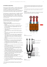
Option 1:
Heat shrink type cable termination using special insulated
terminal protectors as shown in picture below.
CT’s
—
Figure 8.7
CT and cable termination details
—
Figure 8.8
cable termination details
Center Of Cable
Bushing
HVOT - Insulating Tube
Stress Control
Tube
Black Tube-2
Copper
Screen
Black Tube-1
Black Tube-1
(Trifurcation Boot)
Copper
Braid
Binding Wire
Copper
Mesh
Cable Earthing
Braid
Armour

