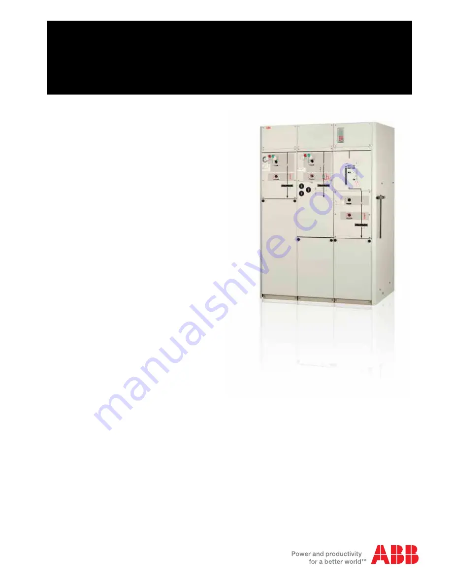
background image

SafeRing / SafePlus 36kV
Installation and operating instructions

1VDD006116 GB

1VDD006116 GB

Summary of Contents for SafeRing 36

Page 1: ...SafeRing SafePlus 36kV Installation and operating instructions 1VDD006116 GB 1VDD006116 GB ...

Page 2: ...Operation 15 5 1 Operating conditions 15 5 2 Operation 16 5 2 1 Switch disconnector C module 16 5 2 2 Earthing switch C module 16 5 2 3 Switch fuse combination 17 5 2 4 Switch disconnector F module 17 5 2 5 Earthing switch F module 17 5 2 6 Vacuum circuit breaker V module 18 5 3 Installation and replacement of fuse links 19 6 Additional equipment 21 6 1 Motor operation and auxiliary switches 21 6 ...

Page 3: ...s a sealed stainless steel tank which contains all the live components and switching functions The transformer is protected by a switch fuse combination or by a vacuum circuit breaker with relay The units modules are delivered from the factory ready for installation Routine tests are carried out on all units modules before dispatch No special tools are required for the installation of units module...

Page 4: ...ce 13 Cable compartment cover 14 Cable bushing 15 Cable support bar 16 Earth bar 17 Pressure indicator additional equipment 18 Capacitive voltage indication additional equipment 19 Short circuit indicator additional equipment 20 Ronis key interlock additional equipment 21 Operating mechanism for vacuum circuit breaker 22 Low voltage compartment 23 Protection relay 24 Current transformers 25 Discon...

Page 5: ... instruction SafeRing SafePlus 36kV 5 1 2 DIMENSIONAL DRAWINGS 1 3 SIDE CONNECTIONS Unit 1 way 2 way 3 way 4 way A mm 490 910 1330 1750 615 F and V modules 1035 C D and De modules L1 L2 L3 L1 L2 L3 A 900 REJ603 L1 L2 L3 379 1930 ...

Page 6: ...its are top heavy so please handle with care 2 1 BY RECEIVING INSPECTION Upon receiving the SafeRing SafePlus please check that the delivered equipment has not been damaged during transport If any such damage has occurred a claim must be submitted to the carrier immediately After unpacking the following must be checked 1 Operating handle 1 piece should be included normally fixed on right hand side...

Page 7: ...1 200 200 2002 630 630 6301 Breaking capacities active load A 630 630 630 200 200 200 closed loop A 630 630 630 200 200 200 off load cable charging A 20 21 21 20 21 21 50 50 50 Class C1 earth fault A 60 63 63 60 63 63 earth fault cable charging A 35 36 36 35 36 36 transfer current A 840 750 750 short circuit breaking current kA see3 20 20 20 Class E1 S1 Making capacity kA 50 50 50 5 times 50 50 50...

Page 8: ... 1YMB531006M0005 40 SafeRing 36 SafePlus 36 F panel 120 load Rated voltage 36 kV Operating voltage 30 kV Itransfer at 36 kV 840 A To 40 ms Transformer rating kVA uk Transformer rated current A ABB Catalogue no Fuse link rated current A 100 4 1 9 1YMB531006M0001 6 125 4 2 4 1YMB531006M0002 10 160 4 3 1 1YMB531006M0002 10 200 4 3 8 1YMB531006M0003 16 250 4 4 8 1YMB531006M0003 16 315 4 6 1 1YMB531006...

Page 9: ...342 13 63 SafeRing 36 SafePlus 36 F panel 120 load Rated voltage 36 kV Operating voltage 30 kV Itransfer at 36 kV 840 A To 40 ms Rated voltage 40 5 kV Operating voltage 35 kV Itransfer at 40 5 kV 750 A To 40 ms Transformer rating kVA uk Transf rated current A SIBA article no Fuse link rated current A Transf rated current A SIBA article no Fuse link rated current A 100 4 1 9 30 008 13 6 3 1 6 30 34...

Page 10: ...itchgear with Internal Arc Classification AFL the following must be considered Unit must be equipped with arc proof cable covers Distance from floor to roof must be minimum 2600 mm Distance from back of unit to wall must be 100 mm Distance from side wall of unit to wall must be minimum 20 mm If unit is freestanding i e distance from back of unit to wall exceeds 100 mm the area behind the unit must...

Page 11: ...can be supplied with interlocking to earthing switches additional equipment When interlocking is fitted the cable compartment can only be accessed when the earthing switch is in the closed position 1 Loosen the two screws on the cable cover 2 Pull out and lift the cover off 3 Removal of front section 4 Front sections removed 13 39 ...

Page 12: ...B Kabeldon Please see supplier documentation for details The manufacturer s installation instructions must be followed Be sure to lubricate the bushings thoroughly with the silicone supplied NOTE Where cables are not connected the earthing switch must be locked in closed position or the bushings must be fitted with dead end receptacles before the unit is put into operation Prefabricated cable term...

Page 13: ...rrent transformer see figure on left and earthed on the earthing bar in the cable compartment A mounting plate for the current transformers is fitted in the cable compartment After the current transformers have been installed in the unit the cables from the protection relay are connected Consult the manual supplied with the protection relay for a description of the connections SafeRing SafePlus wi...

Page 14: ...t be stopped See table for filling pressure below SF6 gas temp Absolute filling pressure o C mbar 0 1305 5 1328 10 1352 15 1376 20 1400 25 1424 30 1448 35 1472 40 1496 4 4 GAS PRESSURE SafeRing SafePlus contain SF6 gas with a nominal pressure of 1 4 bar at 20o C SafeRing SafePlus are sealed for life and is fitted with a temperature compensated pressure indicator Pointer in green area unit has corr...

Page 15: ... the atmospheric pressure will be lower and the overpressure inside the tank will have to be reduced Airfreight Units modules transported by airfreight are delivered with reduced overpressure For topping up please see procedure for topping up of SF6 gas Application of the X ray regulations One of the physical properties of vacuum insulation is the possibility of X ray emissions when the contact ga...

Page 16: ...of the earthing switch 5 2 1 SWITCH DISCONNECTOR 5 2 OPERATION Before any operation of mechanisms make sure that front covers are mounted All switch disconnectoer and earthing switches can be operated with the included operating handle All mechanisms are designed and manufactured in such a way that all three phases are operated simultaneously The speed of operation is independent of the operator a...

Page 17: ...red O button Charged spring inicator shall now show uncharged sprongs arrow pointing uwards 5 2 5 EARTHING SWITCH Earthing switch Before entering handle press interlocking bracket towards left If the earthing switch is open enter the handle with its pin on the left side If the earthing switch is closed enter the handle with its pin on the right side Earthing switch Close Turn the operating handle ...

Page 18: ...Note If the VCB is equipped with motor operation optional it is not necessary to charge the spring by hand The motor starts charging the spring automatically as soon as the auxili ary voltage is switched on Close Push green ON button Open Push red OFF button Note the downstream disconnector is mechanically interlocked with the VCB Operation of the downstream disconnector and earthing switch see po...

Page 19: ...ossible before the blown fuse link s has been replaced Acc to IEC 60282 1 it is advisable to replace all 3 fuse links even if only 1 or 2 has blown Fuse links are replaced as shown in the sequence of illustra tions Switch fuse combinations are supplied without fuse links installed When installing fuse links follow the sequence of illustrations 1 9 1 Before entering handle on to earthing switch pre...

Page 20: ...o be replaced pull it out 6 Fix the new fuse link to the fuse cover by means of the contact screw Note the striker pin must point towards the fuse cover 7 Insert the fuse link into fuse canister 8 Press the handle and close the fuse canister 9 Fix the front cover The switch fuse combination is ready for operation ...

Page 21: ...iliary switch 1NO for monitoring of SF6 pressure Access to the low voltage connections is gained by removing the top front panel 6 2 CAPACITIVE VOLTAGE INDICATION All modules can be equipped with capacitive voltage indication type HR module VDS or VPIS Voltage Present Indicating System acc to IEC 61958 This system has integrated LEDs By means of the sockets in VPIS and HR it is possible to carry o...

Page 22: ...nts will be necessary Check that the lub ricants are not washed or wiped away from the mechanical moving parts 7 1 CONTROL AND MONITORING THE GAS SafeRing SafePlus is a pressure sealed system that nor mally does not require special inspections However the gas pressure on the pressure indicator should always be checked prior to operation 6 5 RONIS KEY INTERLOCK To prevent unintended operations all ...

Page 23: ... conditions exceeding 30 years The switchgear is gas tight with an expected diffusion rate of less than 0 1 per annum Referring to the reference pressure of 1 4 bar the switchgear will maintain gas tightness and a gas pressure better than 1 3 bar at 20o C throughout its designed life span LIFECYCLE CONCEPT FOR TRANSPORT INSTALLATION REPAIR SERVICE AND DISPOSAL AT END OF LIFE ABB is committed to th...

Page 24: ...1VDD006166 GB0513 For more information please contact ABB AS Power Products Division P O Box 108 Sentrum N 3701 Skien Norway Phone 47 35 58 20 00 Fax 47 35 52 41 08 www abb com ...

Reviews: