29
4
5
6
7
8
9
10
11
12
13
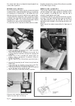
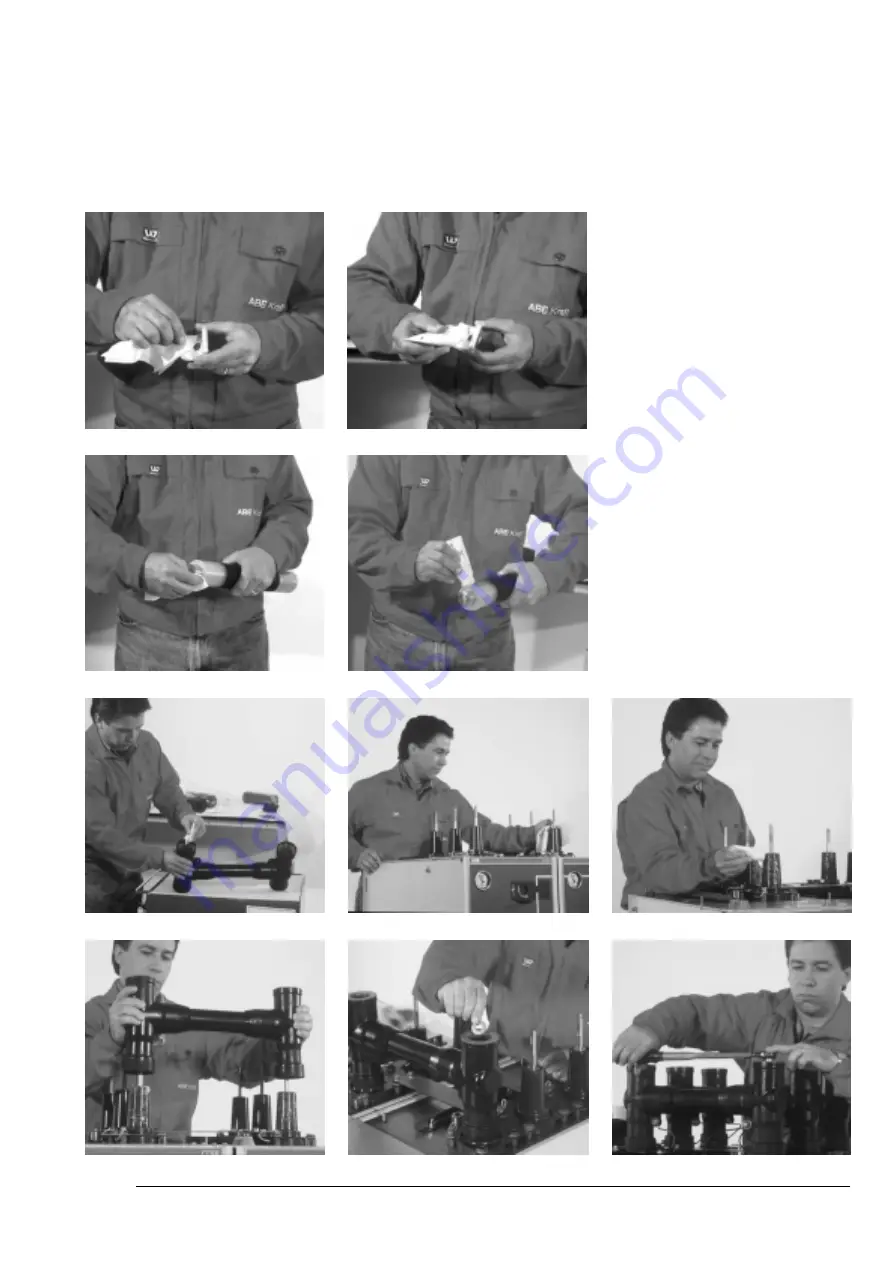
Le scanalature delle piastrine di contatto devono comba-
ciare con il perno filettato. L’adattatore deve sovrapporsi
allo strato nero conduttivo della sbarra. (Foto 4-7)
3. Pulire l’adattatore e il passante (area “B”), quindi ricoprirli
con pasta per montaggio. Inserire l’adattatore sul passan-
te. Avvitare l’asta filettata e la rondella di serraggio con il
dado con una coppia di 50 Nm (Foto 8-13)
The contact plate grooves must match with the threaded
pin. The adapter must lie over the black conductive layer of
the busbar. (Photos 4-7).
3. Clean the adapter and the bushing (area “B”), then cover
them again with assembly paste. Insert the adapter over
the bushing. Screw up the threaded rod and the tightening
washer with the nut using a torque of 50 Nm (Photos 8-13).
Fig. 24

