22
WARNING
Replenishment of SF
6
-gas in SafeRing/SafePlus
Potential risk!
Operators must be trained and qualified for
SF
6
-gas handling
The following equipment is needed: SF
6
-gas bottle with
manometer and reduction valve, bottle for recovery of
SF
6
/air mixture, adapter and pressure measuring device. It is
important that the pressure measuring device shows absolute
pressure. If you have a pressure measuring device showing
over-pressure, please contact ABB for instructions
(NHP 408025).
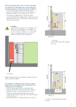
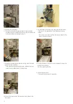
1. Remove the front cover and if possible the top cover.
Unscrew the pressure indicator by unscrewing the hexagon
nut as shown on the figure at the right.
2. Screw the adapter to the valve. The tightening torque is
max 45 Nm.
3. Before connecting the hose from the gas bottle to the
adapter, the air in the hose must be removed by running
SF
6
-gas through the hose. The SF
6
-gas must be recovered.
4. When gas is flowing into the RMU/switchgear, the mano-
meter on the gas bottle has to be observed. When it shows
1,4 bar absolute at ambient temperature 20° Celsius, the
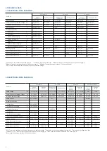
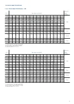
gas filling must be stopped. See table for filling pressure on
next page.
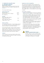
13. PRESSURE INDICATOR
SafeRing / SafePlus is usually supplied with a pressure indi-
cator in the form of a manometer. Additionally, it is possible
to fit a device for an electric signal if the pressure is low. This
requires auxiliary voltage supply.
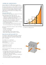
13.1 GAS PRESSURE
SafeRing / SafePlus contain SF
6
-gas with a nominal pressure
of 1,4 bar absolute at 20
o
C.
SafeRing / SafePlus are «sealed for life» and fitted with a
temperature-compensated pressure indicator.
Pointer in green area - unit has sufficient pressure.
Pointer in red area - pressure is too low.
WARNING
Operation when pressure is too low (pointer in
red area):
If pointer is in red area, the operation of the switch-
gear can not be done under live conditions (voltage
on). SF
6
-gas needs to be topped up according to
instruction and the filling table on next page before
operation can be done under live conditions.
For more detailed description, see instruction ma-
nual 1VDD201603
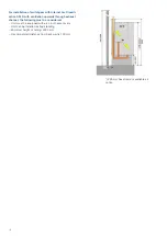
5. Remove the filling hose and connect the pressure device to
check the pressure inside the RMU/switchgear.
6. When the correct pressure of 1,4 bar absolute is obtained,
remove the adapter, check that the sealing between the
pressure indicator and the valve is smooth and clean, and
screw the pressure indicator to the RMU/ switchgear with
tightening torque max 45 Nm as shown below.
Note! Screw/unscrew on this hexagonal
nut only. The pressure indicator can be
dismounted from the switchgear with-
out SF
6
leakage from the SF
6
tank
Spring-loaded
valve
Air
SF
6
CAUTION

