background image

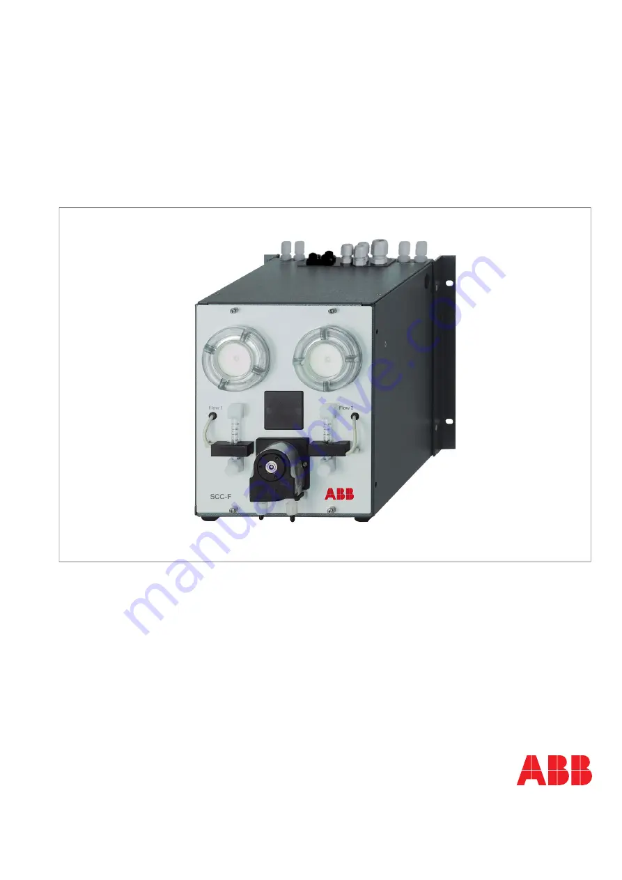
SCC-F   Sample gas feed unit 

Operator’s manual


42/23-51 EN Rev. 3 

Summary of Contents for SCC-F

Page 1: ...SCC F Sample gas feed unit Operator s manual 42 23 51 EN Rev 3 ...

Page 2: ...electrical leads Notes 14 Connecting the electrical leads SCC F without I O card 15 Connecting the electrical leads SCC F with I O card 18 Setting up the I O card in the gas analyzer 22 Connecting the sample gas pipes 22 Power supply activation lead time 23 Chapter 4 Maintenance 24 Replacing the dosing pump hose 24 Replacing the dosing pump pressure rollers and springs 26 Replacing the diaphragm a...

Page 3: ...l be pleased to supply additional information as required Please contact your local service representative For emergencies please contact ABB Service Telephone 49 0 180 5 222580 Telefax 49 0 621 38193129031 E mail automation service de abb com Symbols and typefaces Identifies safety information to be heeded during unit operation in order to avoid risks to the operator Identifies specific informati...

Page 4: ... complies with EN 61010 Part 1 Safety requirements for electrical equipment for measurement control and laboratory use and with standards CAN CSA C22 2 No 61010 1 12 and UL Std No 61010 1 3rd Edition Certificate no 70010607 Version for Class I Div 2 The sample gas feed unit is certified to Class 2258 02 Process Control Equipment For Hazardous Locations Certified to Canadian Standards and Class 225...

Page 5: ... safety precautions for installing and operating electrical devices Safety precautions for working with gases acids condensates etc National regulations The regulations standards and guidelines cited in this operator s manual are applicable in the Federal Republic of Germany The applicable national regulations should be followed when the unit is used in other countries Unit safety and safe operati...

Page 6: ...t be disconnected from all power sources before any maintenance work is performed Charged capacitors The unit capacitors can retain their charge even when the unit is disconnected from all power sources Use of proper fuses Only fuses of the specified type and rated current should be used as replacements Never use patched fuses Do not short circuit the fuse holder contacts When safe operation can n...

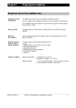
Page 7: ...eed unit should be installed as close as possible to the gas analyzer Adequate air circulation Ensure adequate natural air circulation around the sample gas feed unit Avoid heat accumulation Protection against adverse environ mental conditions The sample gas feed unit should be protected from Cold Radiated heat e g from the sun kilns or boilers Temperature fluctuations Strong air movement Dust dep...

Page 8: ...an the lowest ambient temperature anywhere in the sample gas feed path If this is not the case then a sample gas cooler unit or a condensate trap is required Scope of delivery Scope of delivery Quantity Description 1 SCC F sample gas feed unit 2 Operator s manuals 1 copy in German 1 in English 8 Fastening screws M5 x 12 4 x recessed head 4 x hexagon socket for installing side by side with the SCC ...

Page 9: ...lve 5 Dosing pump 6 Condensate monitor 7 LED display and reset switch for condensate and flow alarm You must take the additional space requirement into account adjacent to the unit on the left hand side for the cooling air inlet approx 10 cm in front of and underneath the unit for running and connecting the reagent pipes to the dosing pump option and above the unit for running and connecting the s...

Page 10: ... out of the unit to the rear the projection of the fixing brackets of around 2 5 cm to the rear wall which is set up in the factory must not be reduced Sample gas feed unit installation in a 19 inch cabinet rack Step Action 1 Unscrew the mounting brackets from the rear of the side covers and screw them securely at the front of the side covers flush with the front cover using the drill holes provid...

Page 11: ...tion facing towards the unit s front panel Figure 2 Dimensional drawing Sample gas feed unit and sample gas cooler side by side Dimensions in mm You must take the additional space requirement into account adjacent to the units on the right hand and left hand side for the cooling air inlet and in front of the units for the cooling air outlet approx 10 cm in each case in front of and underneath the ...

Page 12: ...el and open it forwards the front panel remains attached in the rebate of the base plate 8 Undo the 8 fastening screws on the covering hood release the cable lug of the protective leads from the quick terminal on the inside of the covering hood then lift the covering hood off 9 Remove the dummy plug from the drill hole in the left hand casing panel Screw sample gas feed unit and sample gas cooler ...

Page 13: ...ination Fitting in a 19 inch cabinet rack Unscrew the fixing brackets from the rear of the side panels and screw them securely at the front of the side panels using the drill holes provided for this purpose Fit the feed cooler unit combination to the wall using 4 M6 screws not supplied Fitting to a mounting plate Fit the feed cooler unit combination using 4 M6 screws not supplied The fixing bracke...

Page 14: ...losed JP1 Condensate alarm 1 switches off diaphragm pump 1 Condensate alarm 1 does not switch off diaphragm pump 1 JP2 Condensate alarm 2 switches off diaphragm pump 2 Condensate alarm 2 does not switch off diaphragm pump 2 Connection of the sample gas cooler to the sample gas feed unit If the SCC F sample gas feed unit and the SCC C sample gas cooler are used together e g in an analysis system th...

Page 15: ...er If the sample gas cooler is provided with a signal cable wires 2 C and 3 NO of this cable can be used for this purpose 5 Connect the 3 wire connection cable for the sample gas cooler s power supply to terminals 1 2 and 3 on terminal strip X1 in the sample gas feed unit and to terminals 2 3 and 4 on terminal strip X1 in the sample gas cooler If the sample gas cooler is provided with a power supp...

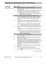
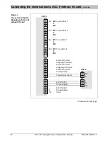
Page 16: ...9 10 3 4 11 12 5 6 13 14 7 8 15 16 X3 X4 X1 3 6 2 5 1 4 SCC F 1 5 2 6 3 7 4 8 L N PE 230 115 VAC NC NC NC NC C C C C NO NO NO NO LA1 LA2 FA1 FA2 NC NC NC NC C C C C NO NO NO NO Power Supply Input Liquid Alarm 1 Liquid Alarm 2 Flow Alarm 1 Flow Alarm 2 External Control Diaphragm Pump 1 External Control Diaphragm Pump 2 External Control Dosing Pump X1 PE N L 3 2 X3 SCC C NO C 230 115 VAC 4 3 2 Tempe...

Page 17: ... of the diaphragm pumps and dosing pump temperature alarm X6 Condensate sensors 1 and 2 flow sensors 1 and 2 internal connections JP1 Internal control of diaphragm pump 1 JP2 Internal control of diaphragm pump 2 Figure 5 Terminal strip positions in the SCC C sample gas cooler X1 Power supply X2 Internal power supply voltage switching X3 Status signal temperature alarm X4 Pt 100 resistance thermome...

Page 18: ...es for the Pt 100 resistance thermometer and power supply of the sample gas cooler delivered with the unit see section Scope of delivery page 8 through the rubber bushing If the sample gas cooler is provided with a signal cable for the temperature alarm this cable should be disconnected from terminal strip X3 since it is not intended to be connected to the I O card 5 Connect the 2 wire connection ...

Page 19: ...re cross section 2 x min 1 5 mm2 flammability class VW 1 and FT 1 temperature resistance ambient temperature 60 C 10 Make sure the power supply leads have an adequately dimensioned protective device breaker max 20 A 11 Install a switched outlet or a breaker in the power supply wiring near the sample gas feed unit This should allow the sample gas feed unit to be completely disconnected from the pow...

Page 20: ...I5 DI6 max 30 V 1 A General Purpose max 30 V 1 A General Purpose N N N 230 115 VAC 1 230 115 VAC 1 230 115 VAC 1 L L L 1 B300 Pilot Duty 360VA max 240 VAC 12 12 to 24 V DC to 24 V DC Power supply input Solenoid valve gas path 1 Solenoid valve gas path 2 Solenoid valve gas path 3 12 12 12 12 12 12 to 24 V DC to 24 V DC to 24 V DC to 24 V DC to 24 V DC to 24 V DC Reagent bottle 1 Level too low Reage...

Page 21: ... internal connection to the connector on the top of the casing X6 Digital inputs DI7 and DI8 X7 Diaphragm pump and solenoid valve gas path 1 dosing pump X8 Condensate sensors 1 and 2 flow sensors 1 and 2 internal connections X9 Service interface RS232 X10 Digital inputs DI1 to DI6 status signals from external devices X11 Service interface Ethernet X16 Digital outputs DO1 and DO2 alarm signals Pt 1...

Page 22: ... label on the I O card The serial number contains the following information example 0 0 6 0 1 6 0 0 0 1 2 3 0 1 Serial number of the I O card Module type 006016 I O card Connecting the sample gas pipes Sample gas connections The sample gas connections are PVDF screw connections for DN 4 6 mm hose The sample gas inlets and outlets on the top of the sample gas feed unit are identified with arrows an...

Page 23: ...time for the sample gas feed unit is approx 10 minutes However the lead time of the connected sample gas cooler is of greater importance In the case of the SCC C sample gas cooler the lead time is approx 15 minutes Status signals The flow alarms are present during the lead time The condensate alarms may also be present Readiness At the end of the lead time period the sample gas feed unit is ready ...

Page 24: ...y 5 months CAUTION Never lubricate the dosing pump hose The hose can contain acid residue These materials can flow out when the hose connections are opened Take appropriate measures where needed to collect residual acid Appropriate precautions should be taken and relevant regulations on disposal should be complied with Replace dosing pump hose see Figure 8 Step Action 1 Stop the sample gas supply ...

Page 25: ...head using the handles press the moving belt together while at the same time turning the S clip 2 counterclockwise until it engages 8 Screw the hoses to the hose connections 4 Take care not to kink or crush the hoses Start the sample gas feed unit again 9 Switch on power supply to feed unit 10 The sample gas flow should only be restarted after the lead time period Figure 8 Dosing pump hose and pum...

Page 26: ...ressure springs 6 out of the hole in the roller mounting 5 and out of the retaining slot in the roller axle 7 Remove the roller axle from the roller mounting and pull the pressure roller 8 off the roller axle 6 Push the new pressure roller 8 onto the roller axle 7 and secure with new pressure springs 6 in the roller mounting 5 Fit the pump head 7 Insert the roller mounting 5 in the pump head 4 and...

Page 27: ...Replacing the dosing pump pressure rollers and springs continued Figure 9 Dosing pump roller mounting 1 Moving belt 2 S clip 3 Nuts for securing the pump head x 2 4 Pump head 5 Roller mounting 6 Pressure springs x 4 7 Roller axle 8 Pressure roller x 2 3 4 1 2 5 7 6 8 ...

Page 28: ...he pump has been feeding may be found on the diaphragm and valve plates These materials can flow out when the diaphragm pump is opened Take appropriate measures where needed to collect such residues The medium being fed may be corrosive and poisonous Appropriate pre cautions must be taken Figure 10 Diaphragm pump 1 Head cap 2 Head cap screws 3 Spacer plate 4 Structural diaphragm 5 Casing 6 Connect...

Page 29: ...otating the fan impeller to its upper return point 7 Hold opposite sides of the structural diaphragm raise it and then remove it by rotating in a counterclockwise direction During this procedure you should take care to ensure that the Belleville spring 11 and the distance ring s 12 do not fall from the structural membrane s threaded bolt into the casing 8 Remove the Belleville spring 11 and distan...

Page 30: ...g rings in the spacer plate Fit the pump head 19 Using the fan impeller move the structural diaphragm to its upper dead point 20 Place the spacer plate 3 the valve plates 7 sealing rings 8 and the head cap 1 on the casing in accordance with the markings 21 Check that the head cap is centered correctly by moving it gently sideways 22 Tighten the head cap screws 2 crosswise only slightly 23 Check th...

Page 31: ...supply Fuse blown Replace fuse 5x20 mm T6 3H250V Pump motor blocked Remove blockage Defective pump Replace pump Defective diaphragm Replace diaphragm see page 28 Drops of condensate in the condensate monitor or flow monitor liquid alarm Condensate being produced by the gas analysis system Fluid from the process penetrating Sample gas cooler s condensate collecting vessel full 1 Check operability o...

Page 32: ...power supply 2 Shut off the sample gas supply to the sample gas feed unit 3 Remove the gas pipes from the connections on the sample gas feed unit 4 Thoroughly purge the sample gas feed unit gas paths with an inert gas 5 Fully tighten the gas connections 6 Remove the electrical cables from the sample gas feed unit connections Make sure the sample gas feed unit is free of residual moisture that can ...

Page 33: ...tionally place the sample gas feed unit in a 0 2 mm thick polyethylene bag add a drying agent such as silica gel and seal the bag air tight Use an amount of drying agent appropriate for the package volume and the planned shipping schedule at least 3 months 2 Place the sample gas feed unit in an adequately sized box lined with cushioning material foam or similar substance The cushioning material s ...

Page 34: ...tion with the SCC C sample gas cooler The SCC F sample gas feed unit can be used in conjunction with the SCC C sample gas cooler The functions of the SCC C sample gas cooler are Cooling the sample gas Separating off the condensate and Removing the condensate Reagent dosing The peristaltic hose pump for reagent dosing is installed as an option either in the sample gas feed unit Catalog No 23212 0 x...

Page 35: ...eding the sample gas One or two flow monitors with needle valves One or two condensate monitors One peristaltic pump for reagent dosing optional and A discharge controller only in the version for bypass operation The switching amplifiers for operating and analyzing the flow and condensate monitors are integrated in the electronic processing unit Figure 11 Circuit diagram Version without I O card ...

Page 36: ...onitor 1 flow monitor 1 diaphragm pump Figure 13 Version Catalog No 23212 0 12xxxx000000 2 separate gas feed paths with 1 condensate monitor 1 flow monitor and 1 diaphragm pump each Figure 14 Version Catalog No 23212 0 13xxxx000000 1 gas feed path with 1 condensate monitor 1 diaphragm pump 2 flow monitors e g for NOx measurement Continued on next page 1 1 1 1 2 2 1 1 2 ...

Page 37: ...re 16 Version Catalog No 23212 0 15xxxx000000 2 separate gas feed paths with 1 condensate monitor and 1 flow monitor each and 1 diaphragm pump in first gas feed path with external pump in second gas feed path Figure 17 Version Catalog No 23212 0 16xxxx000000 2 separate gas feed paths with 1 condensate monitor each 1 flow monitor in first gas feed path and 1 diaphragm pump in second gas feed path e...

Page 38: ...essage Failure and shut down of the sample gas pumps and the dosing pump if the cooler temperature is too high Monitoring for break out of condensation Status message Failure and shut down of the sample gas pumps and the dosing pump at break out of condensation Monitoring of the sample gas flow rate Status message Maintenance request if the sample gas flow rate is too low Monitoring of the level o...

Page 39: ... time Approx 10 min plus cooler lead time Dead volume Approx 10 cm3 plus dead volume of heat exchanger Gas seal integrity 5 x 10 6 hPa l s Pressure hPa Flow rate l h Inlet pressure 50 100 150 200 250 800 600 400 200 0 200 400 600 800 400 hPa 3 0 0 h P a 0 h P a 100 hPa 200 hPa A B 50 100 150 200 250 300 350 1000 500 0 500 1000 1500 2000 2500 Pressure hPa Flow l h ...

Page 40: ...gas cooler 11 Dosing pump Replace hose 24 Replace pressure rollers and springs 26 Gas connections 22 Gas pipe connection 22 I O card Connecting the electrical leads 18 Page Connection diagram 20 Description 38 Serial number 22 Setting up in the gas analyzer 22 Terminal strip positions 21 Installation 10 11 Installation site 7 Intended application 4 Operating specifications 39 Pneumatic diagrams 36...

Page 41: ......

Page 42: ...inuous product improvement and the right is reserved to modify the information contained herein without notice Printed in the Fed Rep of Germany 04 15 ABB 2015 42 23 51 EN Rev 3 ABB Automation GmbH Analytical Stierstaedter Strasse 5 60488 Frankfurt am Main Germany Fax 49 69 7930 4566 E Mail cga de abb com 3KXG171202R4201 ...

Reviews: