18
SCC-F Sample gas feed unit Operator’s manual
42/23-51 EN Rev. 3
Connecting the electrical leads: SCC-F with I/O card
Connecting the
electrical leads
(see Figures 5, 6 and 7)
Step Action
Connect signal and control leads to the sample gas feed unit:
1
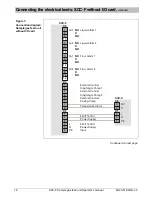
Connect the status signal leads of the external devices (e.g. conden-
sate collecting bottle, reagent supply bottle) to terminal strips
X10
(digital inputs DI1 – DI6) and
X6
(digital inputs DI7 – DI8). Tightening
torque of the screws 0.22–0.25 Nm.
Before connecting the leads remove the factory-installed wire
jumpers from the respective terminals. Do not remove the wire
jumpers from the unused terminals.
2
Connect the alarm signal leads to terminal strip
X16
(digital outputs
DO1 and DO2). Tightening torque of the screws 0.22–0.25 Nm.
3
Connect the leads of the external solenoid valves (e.g. for zero gas
injection)
to terminals 8 and 9 on terminal strip
X7
(gas feed path 1) and/or
to terminals 5 and 6 on terminal strip
X4
(gas feed path 2) and/or
to terminals 7 and 8 on terminal strip
X4
(gas feed path 3).
Tightening torque of the screws 0.5–0.6 Nm.
Observe the polarity of the connections!
If necessary connect the sample gas cooler to the sample gas feed unit:
4
Side-by-side installation: Pull both connection cables for the Pt 100
resistance thermometer and power supply of the sample gas cooler
(delivered with the unit, see section “Scope of delivery”, page 8)
through the rubber bushing.
If the sample gas cooler is provided with a signal cable for the
temperature alarm this cable should be disconnected from
terminal strip
X3
since it is not intended to be connected to the
I/O card.
5
Connect the 2-wire connection cable for the Pt 100 resistance thermo-
meter
to terminals 7 and 8 on terminal strip
X16
in the sample gas feed unit
and
to terminals 1 and 2 on terminal strip
X4
in the sample gas cooler.
Tightening torque of the screws 0.22–0.25 Nm.
The Pt 100 resistance thermometer is connected to terminals 3
and 4 on terminal strip
X4
in the sample gas cooler.
6
Connect the 3-wire connection cable for the sample gas cooler’s power
supply
to terminals L, N and PE on terminal strip
X3
in the sample gas feed
unit and
to terminals 2, 3 and 4 on terminal strip
X1
in the sample gas cooler.
Tightening torque of the screws 0.5–0.6 Nm.
If the sample gas cooler is provided with a power supply cable
this cable can be used to connect the sample gas feed unit to
the power supply (see step 12).
Connect the sample gas feed unit to the system bus:
7
Attach a T-piece to the system bus connector on the top of the
sample gas feed unit casing.
Connect the system bus cable to the T-piece.
Connect a termination resistor to the free end of the T-piece.
Continued on next page


