42/23-51 EN Rev. 3
SCC-F Sample gas feed unit Operator’s manual
21
Connecting the electrical leads: SCC-F with I/O card,
continued
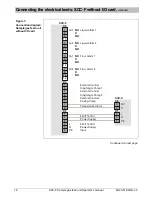
Figure 7
Terminal strip posi-
tions on the I/O card
in the sample gas
feed unit
X1
Power supply input
X2
Ground
X3
Power supply output (to SCC-C sample gas cooler)
X4
Diaphragm pump and solenoid valve gas feed paths 2 and 3
X5
System bus (internal connection to the connector on the top of the casing)
X6
Digital inputs DI7 and DI8
X7
Diaphragm pump and solenoid valve gas path 1, dosing pump
X8
Condensate sensors 1 and 2, flow sensors 1 and 2 (internal connections)
X9
Service interface (RS232)
X10
Digital inputs DI1 to DI6 (status signals from external devices)
X11
Service interface (Ethernet)
X16
Digital outputs DO1 and DO2 (alarm signals), Pt 100 input (from SCC-C)
For information on the system bus structure and I/O card functions refer to section
“I/O card” (see page 38).
X16
X4
X7
X3
X2
X1
X8
X11
X6
X9
X10
X5


