38
A
Annex • 31
C
Checking Gas Path Seal Integrity •
26, 27
Circuit Diagrams • 35
Connecting the Electrical Leads •
14
Connecting the Gas Lines • 13
D
Dimensional Drawing • 9
M
Maintenance • 20
Mounting the Sample Gas Feed
Unit • 11
P
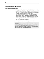
Packing the Sample Gas Feed Unit
• 30
Peltier Cooler Control • 19
Pneumatic Diagrams • 31
Power Supply and Sample Gas
Activation • 17
Preface • 3
Preparation for Installation • 7
R
Replacing the Condensate Pump
Hose • 20
Replacing the Condensate Pump
Pressure Rollers and Springs • 22
Replacing the Diaphragm and Valve
Plates in the Diaphragm Pump •
24
Requirements for the Installation
Site, Power Supply • 7
S
Safety Information • 4
Safety Instructions • 5
Sample Gas Feed Unit Installation •
10
Sample Gas Feed Unit Start-Up •
17
Sample Gas Inlet Conditions • 8
Sample Gas Pump Control • 18
Scope of Delivery • 8
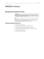
Shutting Down and Packing • 29
Shutting Down the Sample Gas
Feed Unit • 29
Specified Use • 4
T
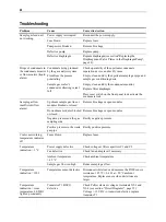
Troubleshooting • 28
U
Unpacking the Sample Gas Feed
Unit • 10
Index
Summary of Contents for SCC-S
Page 1: ...SCC S Sample gas feed unit Operator s Manual 42 23 59 EN Rev 1 ...
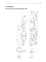
Page 35: ...35 Circuit Diagrams SCC S Sample Gas Feed Unit without Peltier Cooler ...
Page 36: ...36 SCC S Sample Gas Feed Unit with Peltier Cooler ...
Page 37: ...37 SCC S Sample Gas Feed Unit 24 VDC Power Supply and Solenoid Valves ...
Page 39: ......


