9
Dimensional Drawing
Dimensional drawing (dimensions in mm)
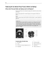
1
Sample gas inlet
2
Sample gas outlet, bypass outlet and test gas inlets via ball valve or solenoid
valve
3
Power supply connection and electrical connection for status signal, solenoid
valve control and 24 VDC
4
Ball valve for infeed of test gas
5
Flow monitor with needle valve (Option: second flow monitor for bypass)
6
Peristaltic pump (Option: second peristaltic pump for external cooler)
7
Membrane filter or condensate monitor
8
LED indicator for condensate alarm, red
9
Pump switch
10
Temperature controller for cooler
NOTE
When mounting, allow for the additional space required for the cooling air outlet
on the left and right side of the unit (min. 3.5 cm).
Remark: The illustration shows options. The scope and features of the ordered
version may differ.
Summary of Contents for SCC-S
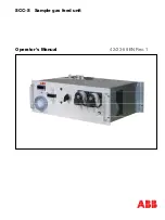
Page 1: ...SCC S Sample gas feed unit Operator s Manual 42 23 59 EN Rev 1 ...
Page 35: ...35 Circuit Diagrams SCC S Sample Gas Feed Unit without Peltier Cooler ...
Page 36: ...36 SCC S Sample Gas Feed Unit with Peltier Cooler ...
Page 37: ...37 SCC S Sample Gas Feed Unit 24 VDC Power Supply and Solenoid Valves ...
Page 39: ......

