2TLC172249M0201, REV. C 2021-10-12
6
3
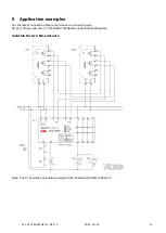
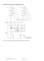
Connections
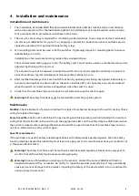
See Chapter Installation and Maintenance for more information regarding installation.
Connections
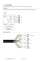
For all ABB switches the NC circuits are closed when the guard is closed and the actuator present.
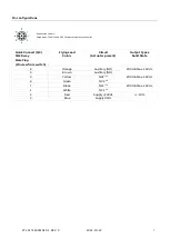
Cable configurations
BLACK (IN)
RED
(24VDC)
POWER
&
&
&
RECEIVER 1
RECEIVER 2
ACTUATOR
BLUE
(0VDC)
WHITE (OUT)
YELLOW (IN)
GREEN (OUT)
ORANGE (IN)
BROWN (OUT)
NC
Circuit 1
NC
Circuit 2
NO
Circuit
RED (24VDC)
BLUE (0VDC)
BLACK (IN)
WHITE (OUT)
GREEN (OUT)
YELLOW (IN)
BROWN (OUT)
ORANGE (IN)
External Supply 24VDC
NC
Circuit 1
NC
Circuit 2
NO
Circuit


